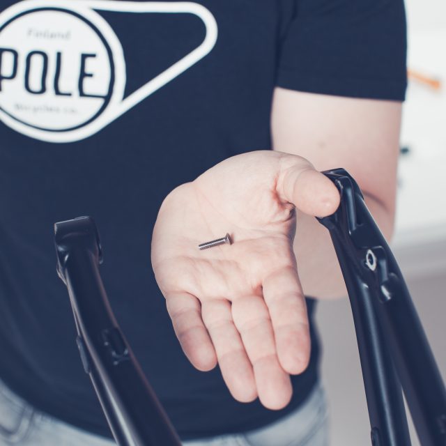
Congratulations, your bike has arrived! You are most likely anxious and in a hurry to get your bike to the trails.
No worries, you are allowed to be stoked, you are about to assemble your new Pole Bike.
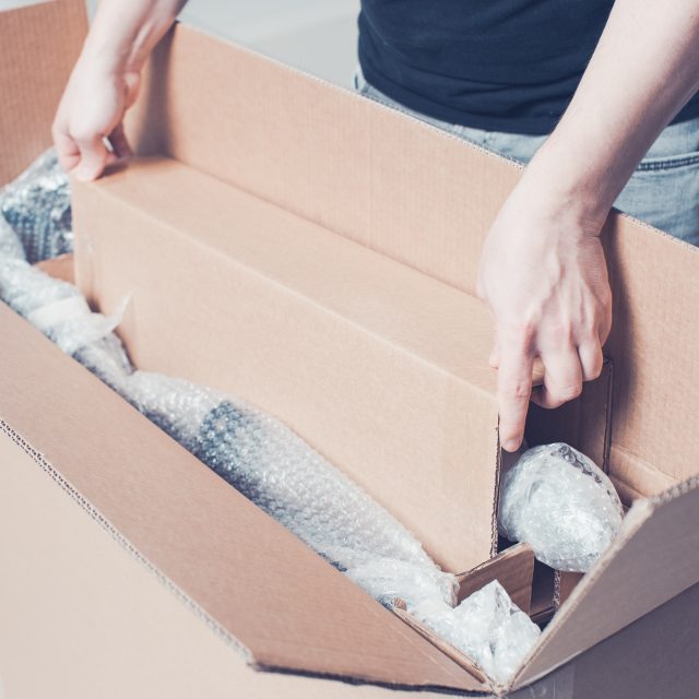
We at Pole have already assembled your bike once and we have tested that everything works properly. After the test ride, we disassemble the bike and pack it for shipping.
We ship the bikes a little bit differently depending on your location.
If you have ordered your bike to be delivered into EU-country, we shall ship the complete bike in one large carton. But if you live outside EU we deliver you complete bike in two separate cartons. The heavier carton contains everything else except the wheelset. The wheelset has been shipped in their own carton. This is because of the transportation costs.
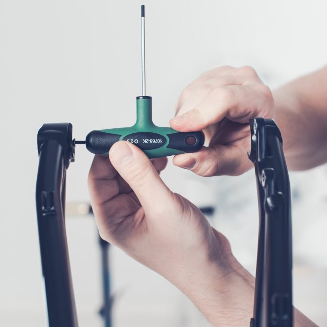
Assembly tools
Your bike is assembled, test-driven and disassembled for packaging at the factory. For the assembly, you need the following tools and bike maintenance products.
Torque wrench with Allen key adapter size 4, 5, 6 and 8 mm
Torque wrench with Torx key size T25
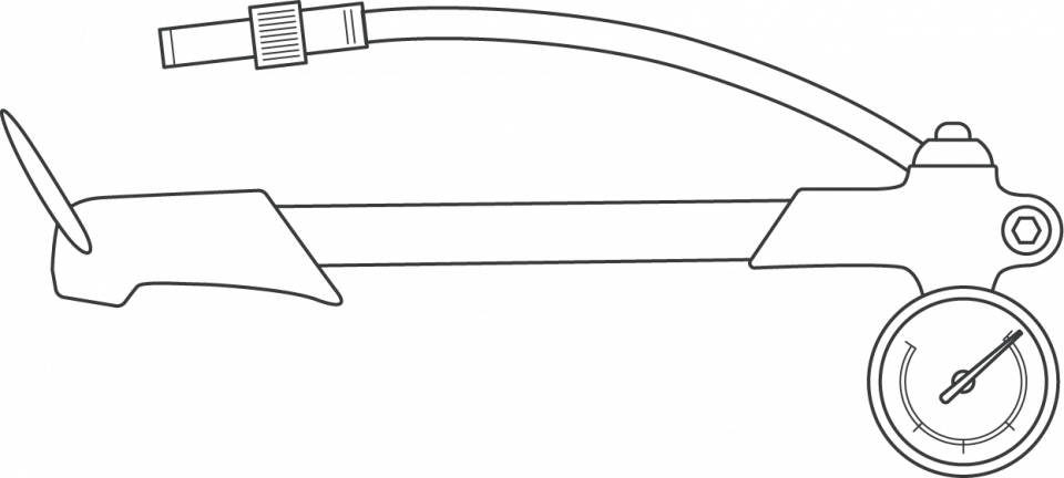
Wirecutter
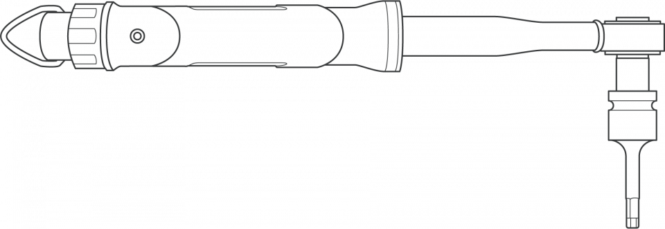
Shock pump
Tire pump
1.2.Assembly products
For assembling the pivot axles, the recommended products are Park Tool ASC-1 grease on threads and Park Tool HPG-1 grease on the axle surface. Do not use copper paste or any other product not mentioned in the installation instructions during the assembly.
1.3.Torques
Bottom bracket
33 – 41 Nm
Brake caliper screw to frame and fork
9,5 Nm
shifter
2,5 – 4 nm
disc brake bolts to hub
6 nm
rear derailleur (fixing bolts)
8 – 10 nm
rear derailleur (clamp bolt)
4 – 5 nm
brake lever
2,8 – 3,4 nm
cassette retainer ring
40 nm
handlebar clamp (carbon / aluminum)
6 nm
stem (steerer tube clamping)
9,5 nm
crank bolts
48 – 54 nm
chainring bolts
12-14 nm (steel), 8-9 nm (aluminum)
pedals
38 nm
lock-on grip bolts
2,5 – 4 nm
shock bolts
10 – 12 nm
axles
20 nm
CAUTION!
These specifications are only guidelines. As a rule, you should always observe the manufacturers’ instructions. These have also been included or can be found on the website of the respective manufacturer.
If you have ordered a Pole frameset, you should receive these items:
Frame
In full suspension bike, the rear shock
*Headset
*Rear axle
*Cable routing kit
*Boost brothers kit – 142 and 148 options (where available)
Seat Clamp
*Certificate
*Receipt
*If you have ordered something additional, E.g. spare hanger or t-shirt, or Huck Norris
* Are packed in one separate carton
At this point, we hope that you have already done the unboxing part of the manuals. Next steps shows you how to assemble the rest of the delivered frameset.
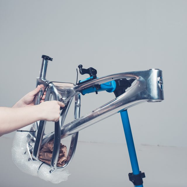
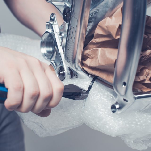
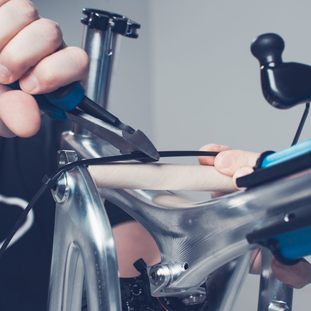
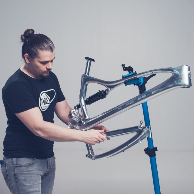
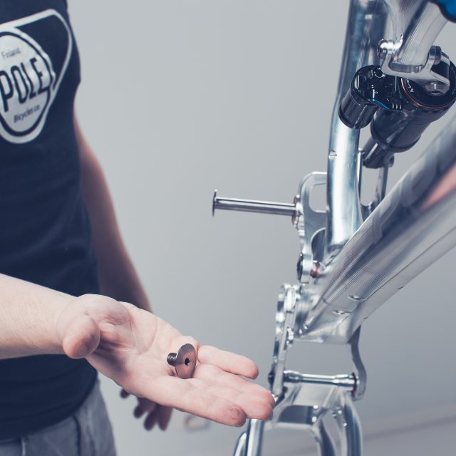
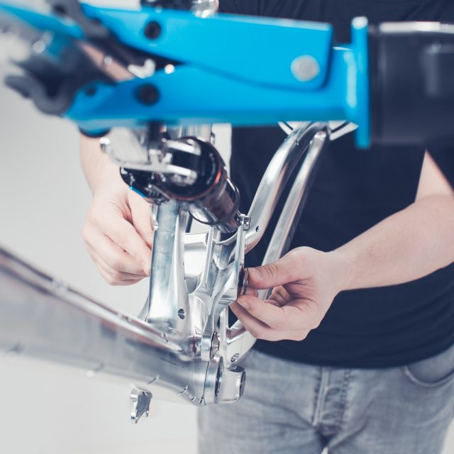
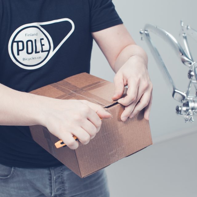
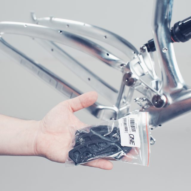
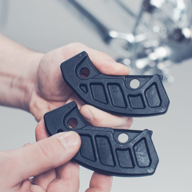
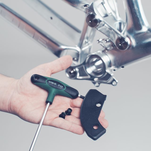
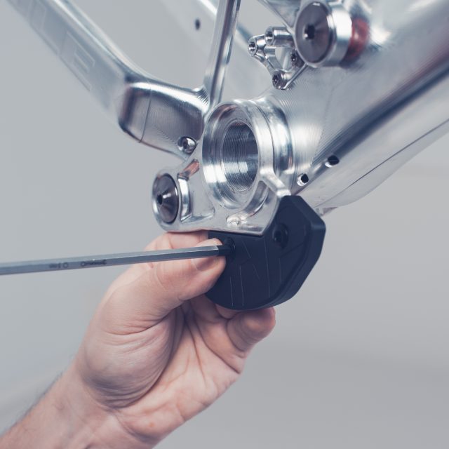
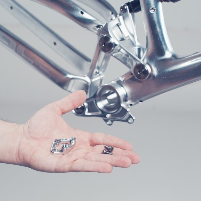
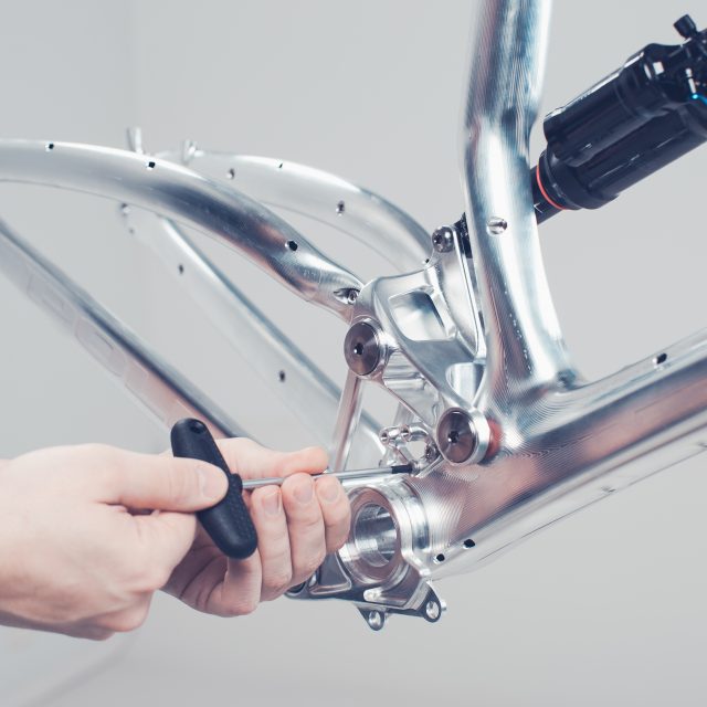
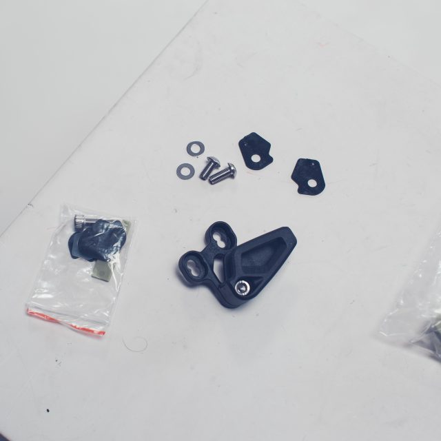
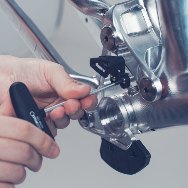
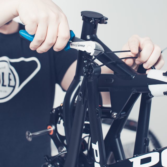
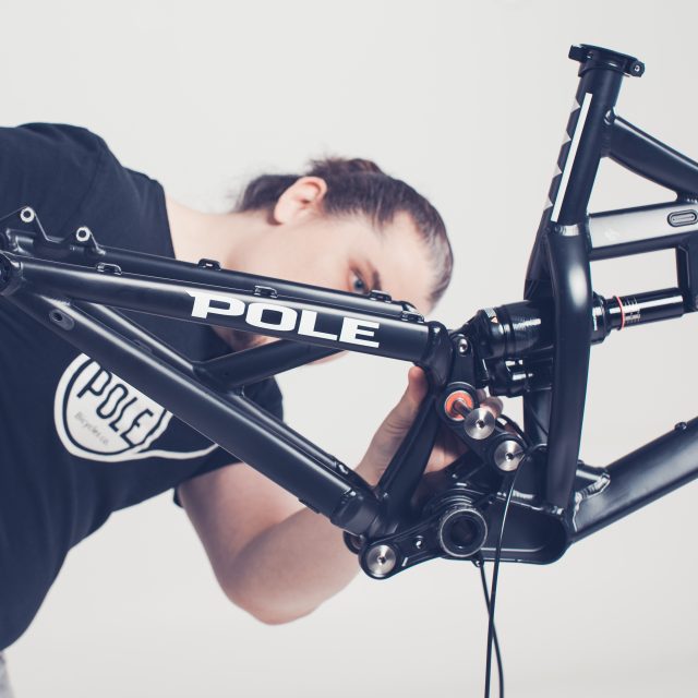
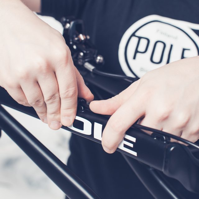
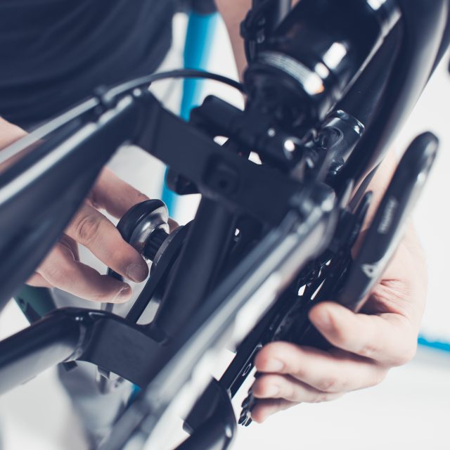
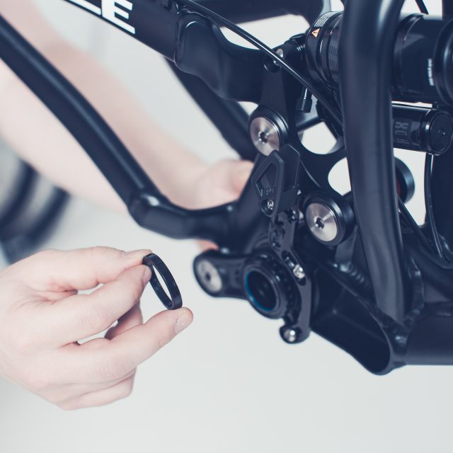
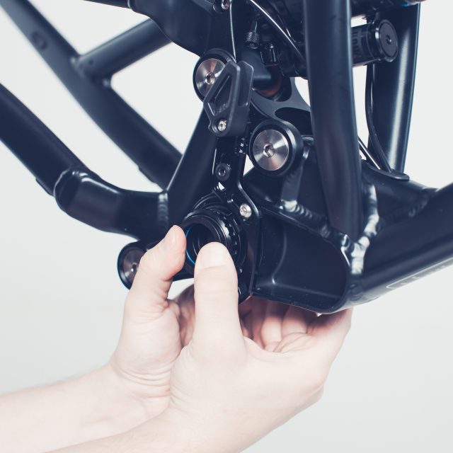
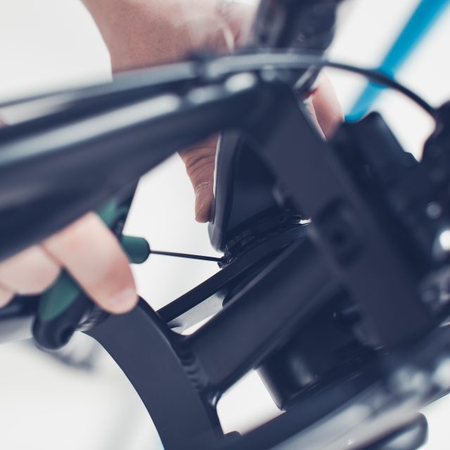
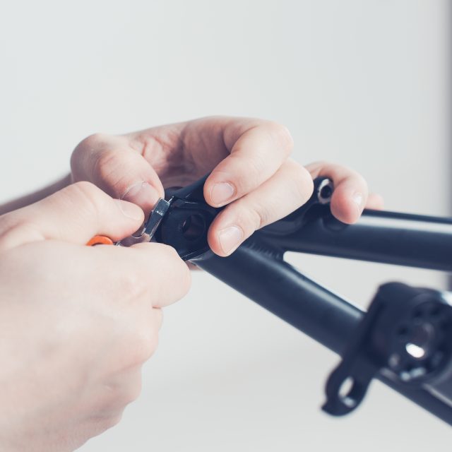
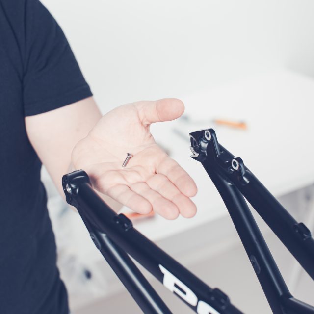
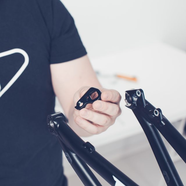
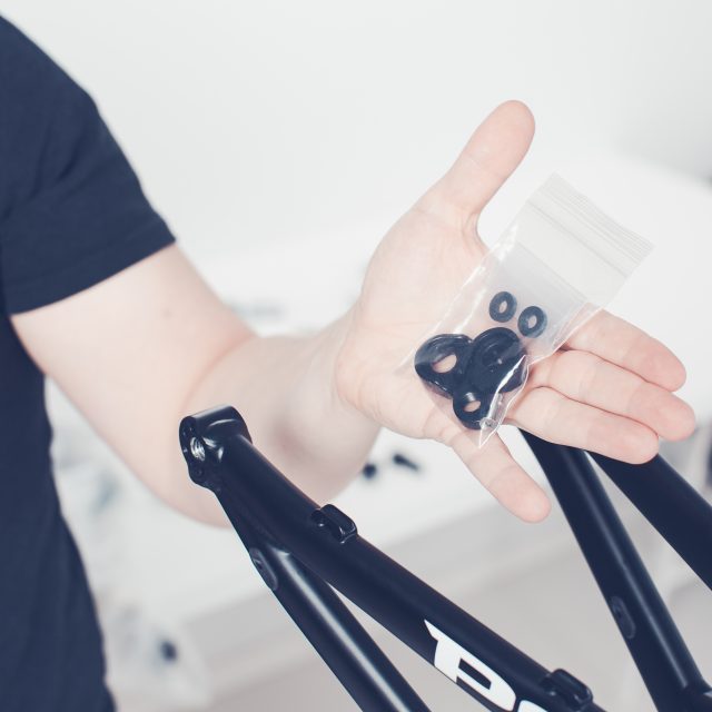
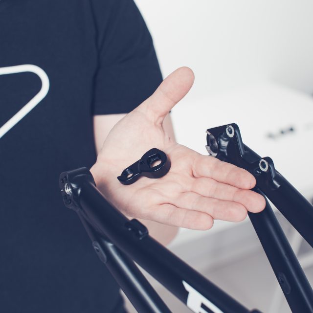
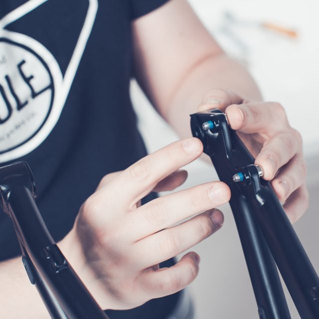
1. You should be on this stage. Take the wire cutters and remove the packing materials from the swingarm. Always prefer clamping from the seatpost instead of the frame. If clamping the frame to a repair stand, use cushioning material between the clamp and the frame and avoid excessive tightening of the clamp. Frames are not designed to withstand high clamping forces.2. When you cut the zip tie(s) which are holding the swingarm folded in place, be careful and hold the swingarm so that it doesn’t fall and damage itself.3. Unfold the frame by following the lower linkage way.4. Remove the upper linkage rear axle.5. Slide the swingarm between the upper link and line the axle with bearings.6. push the axle in place from the drive side only.7. Take the bolt for the axle and screw it to the axle.8. Unbox the additional small parts carton.9. Take the bash guard (Only comes with the machine)10. Check that bash guard size matches your crank sprocket teeth amount. If you are using smaller sprocket than 32T then you should fit 32T bash guard. If you plan to use different size of sprockets you can install the bash guard which is same size as your largest sprocket.11. Take a 5mm Allen key and find the two bolts for the bash guard…and suitable bash guard.12. Install the bash guard.13. Next find the chain guide direct mount and mounting bolts (T25) from the parts carton.14. Install the mount by using T25 Torx15. Find the chain guide. The amount of spacers you need is dependable of the cranks you are using. If you are using SRAM Boost cranks, you should be OK by adding two black spacers under the guide. You can add the spacers later after you have installed the crankset and chain.16. Tighten the chain guide. Use T25 Torx.
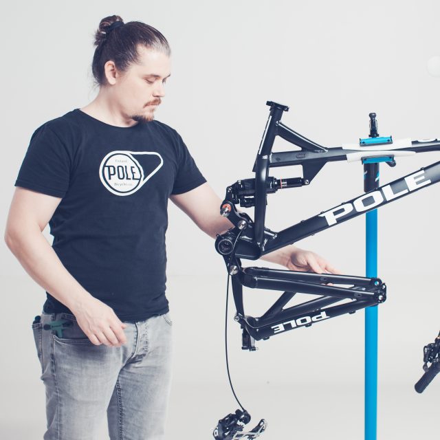
Now the frameset is basically assembled. You can find more assembly instructions by following, for example, the complete bike assembly manual.
1.5.Complete bike
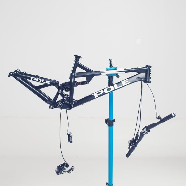
If your bike has been delivered in a single carton you can skip a few parts of this manual. But you should be in a stage where your frame is lifted from the carton and is attached to a bike stand.
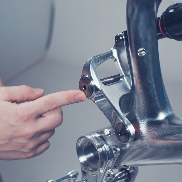
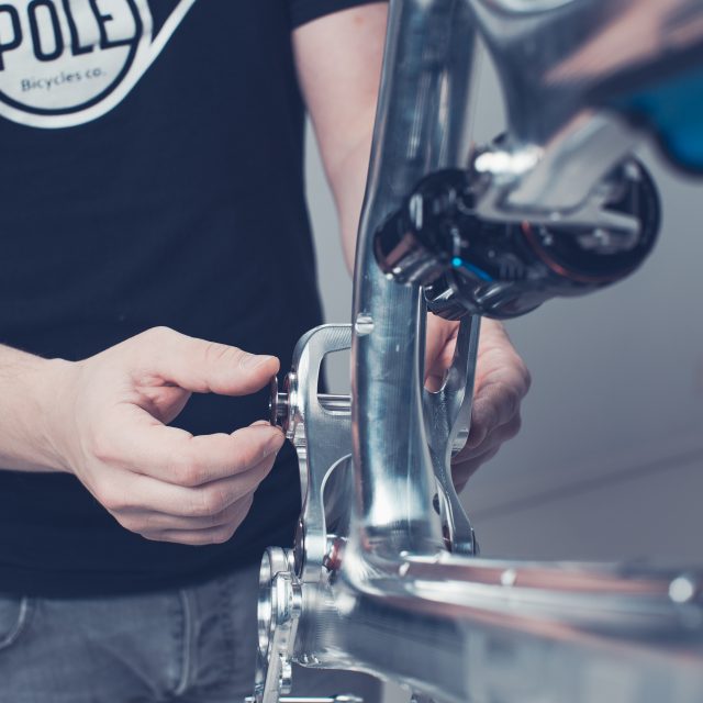
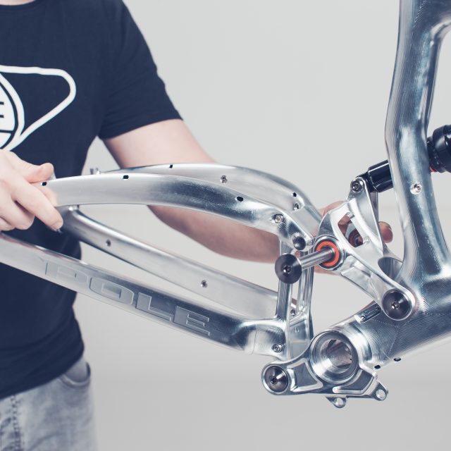
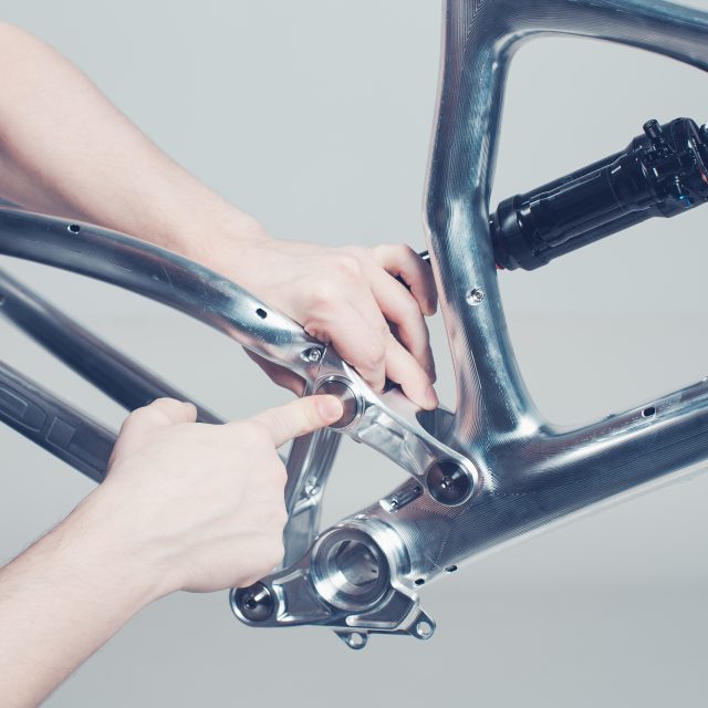
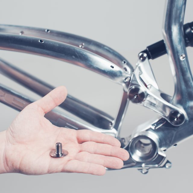
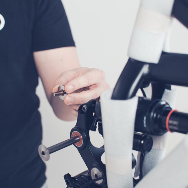
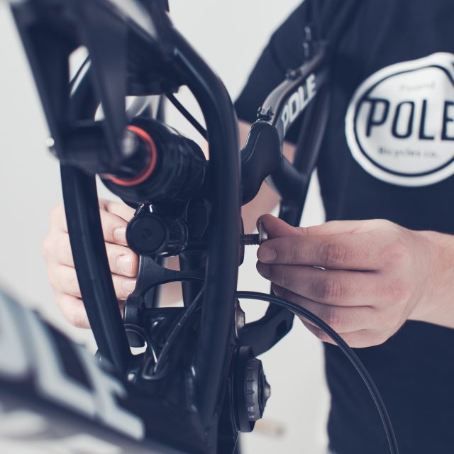
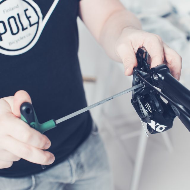
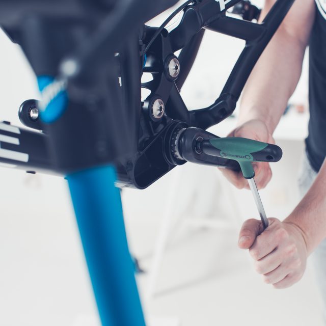
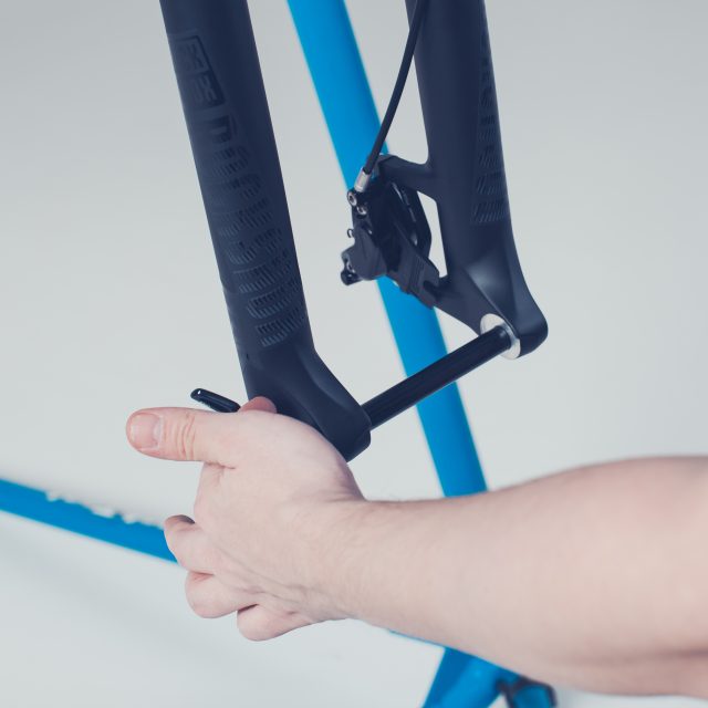
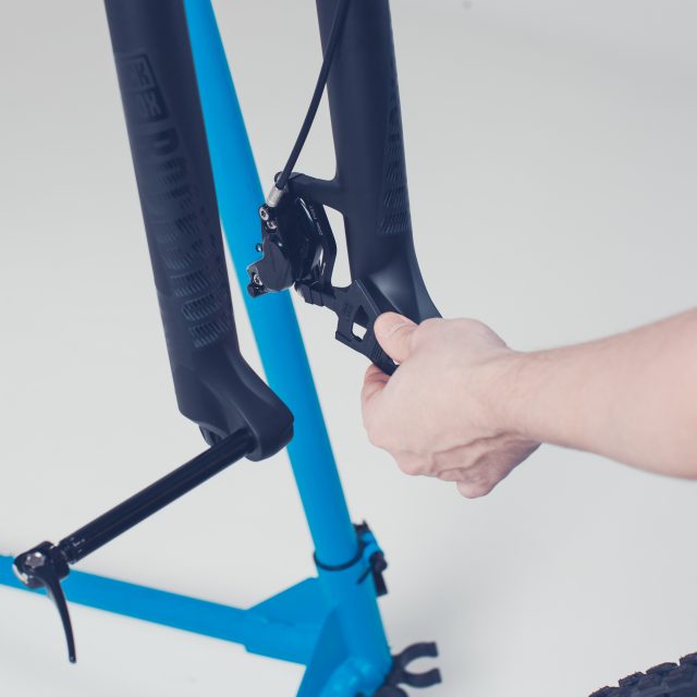
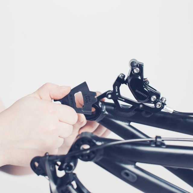
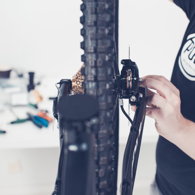
The bike has been delivered in two separate cartons.The bike has been delivered in one large carton.1. Use cable cutters to cut the zip ties and remove all packing material from the frame.2. Remove the bolt and axle from the upper link.3. Unfold the swingarm. Be careful not to harm the frame or the cables going to rear derailleur and rear caliper.4. Slide the swingarm between the upper link.5. Align the axle with swing arm and push the axle thru.6. Screw the bolt in the axle. If you want you can tighten the axle in this stage. Use a torque wrench and tighten to 20Nm.7. Now your bike should look something like this. If you received your bike in one large carton you should have fork and seatpost already installed.8. Screw the rear caliper in its place. Brakes have been adjusted at the factory so you shouldn’t need to adjust brakes, just install and tighten the bolts to 9,5Nm
Upcoming manuals are split so it would be easier for you to follow the steps.
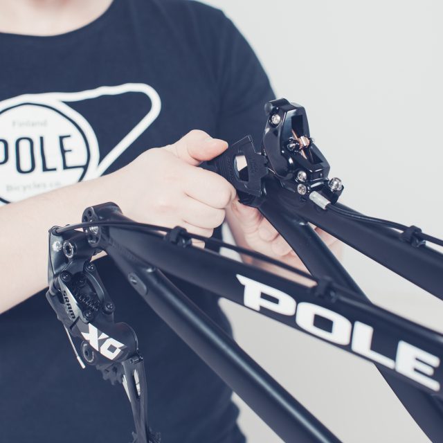
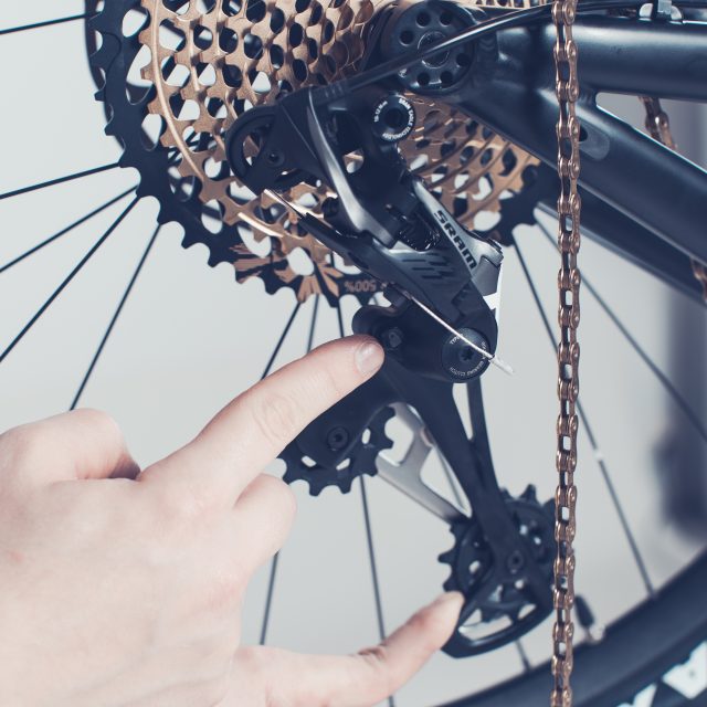
2.Rear Derailleur installation
The rear derailleur is basically your transmission which is controlled by the trigger in the handlebar. Installing the rear derailleur in the assembly stage is pretty straightforward because the gear changing and limiters are adjusted at the factory. You just need to tighten the derailleur back to the hanger.
You can also check manufacturers manual from here. There is more detailed information if you don’t feel confident to install it.
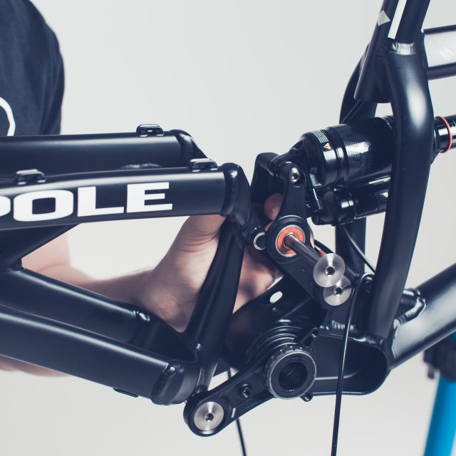
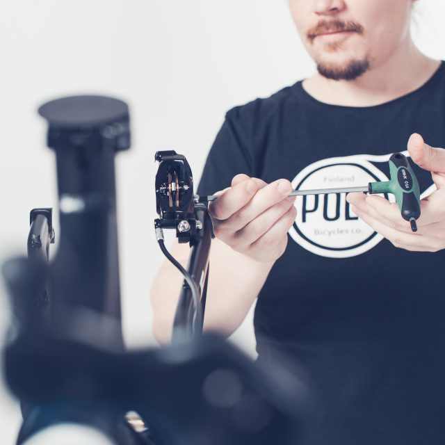
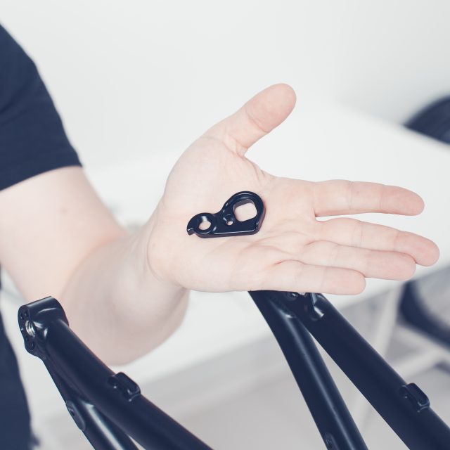
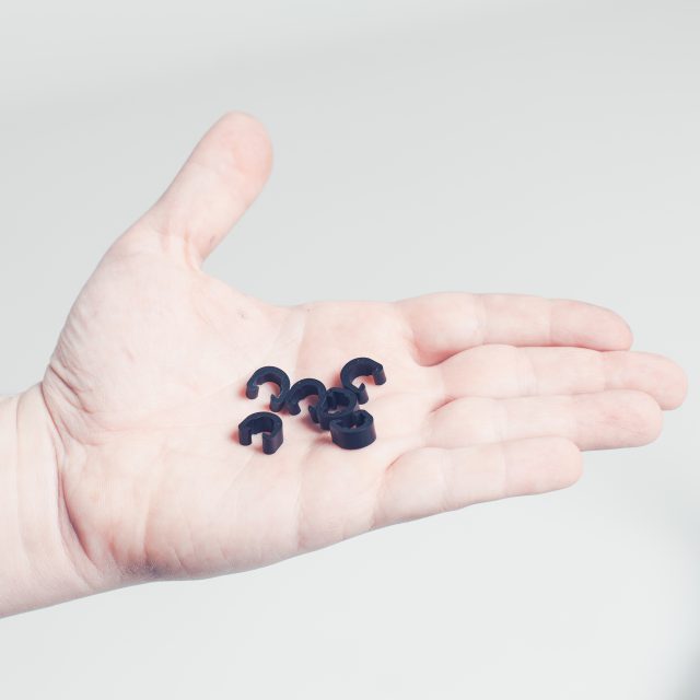
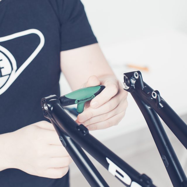
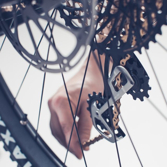
1. The rear derailleur is attached to a hanger, which works like a fuse if you hit your derailleur for a rock or a branch so you won’t break your derailleur. The hanger is attached to a right side dropout.2. Use a 5mm Allen key to tighten the derailleur to the hanger. Tighten to 10-12Nm.3. After you have installed both, the rear derailleur and the rear brake caliper take the cable clamps and install those to the swingarm.4. For this you won’t need any tools, just take a firm grip and press with enough force. You should get those snapped on the place.
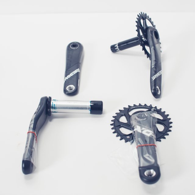
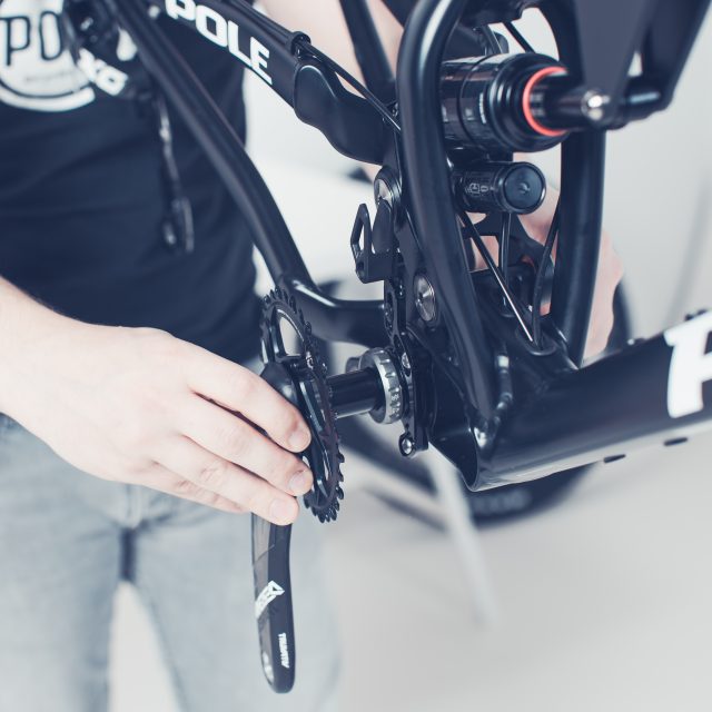
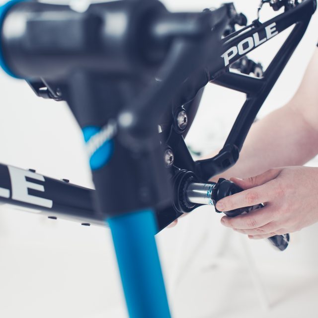
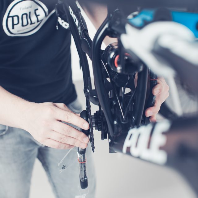
3.Crankset assembly (SRAM GXP)
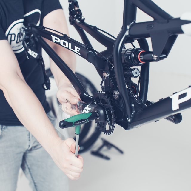
1. Next step is to install cranks. Most likely you have received cranks which are either GXP (upper) or DUB (lower) bottom bracket compatible. The difference you can see above.2. Let’s do the GXP first. First, check that you have the dust ring in place on the non-drive side.3. Install the crank with the spindle (axle) first. In GXP it’s the drive side crank. Hold the dust ring in place with your other and at the non-drive side when you push the crank thru.4. Install the non-drive side crank so that the crank points at the opposite direction compared to drive side crank. In the photo, the drive side is facing directly up and the non-drive side goes in place when facing straight down.5. Take 8mm Allen key and install it to the non-drive side crank. (There is a cap which has a place for 10mm Allen key but you don’t need to use that in this point. It’s only needed when you want to replace the 8mm Allen key bolt under that cap). When you have tightened it so that it feels a bit tight but still turns, swap your tool to a torque wrench and tighten the bolt between 48-54 Nm.
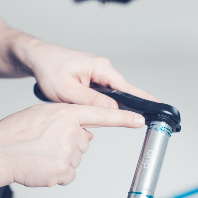
4.Crankset assembly (SRAM DUB)
1. DUB crankset has the spindle/axle on the non-drive side cranks.2. Check that your bottom bracket has the spacer installed…3. The small ridge on the other side of the spacer goes into groove found the bottom bracket. You need to press a little bit harder to lock the spacer correctly.4. DUB cranks have preload system in the non-drive side crank. Open (don’t remove) the bolt with 2mm Allen key.5. Rotate the preload ring towards the crankarm (clockwise).6. Install the non-drive side crank by pushing it thru the bottom bracket.7. Install the drive side crank so that the crank points at the opposite direction compared to non-drive side crank. In the photo, the non-drive side is facing directly up and the drive side goes in place when facing straight down.8. Take 8mm Allen key and install it to the drive side crank. (There is a cap which has a place for 10mm Allen key but you don’t need to use that in this point. It’s only needed when you want to replace the 8mm Allen key bolt under that cap). When you have tightened it so that it feels a bit tight but still turns, swap your tool to a torque wrench and tighten the bolt to 54 Nm.9. Remove play from the system by turning the preload adjuster in the + direction until it stops or makes contact with the bearing shield. Use a 2 mm Allen key to tighten the bolt until the adjuster edges touch.
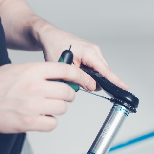
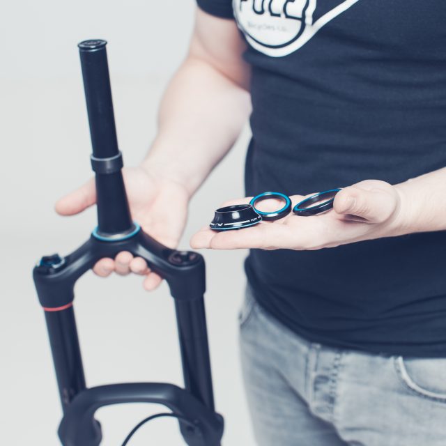
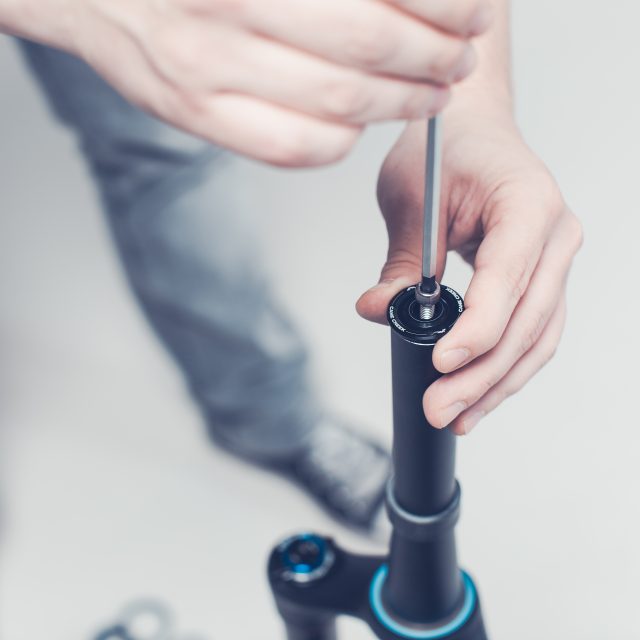
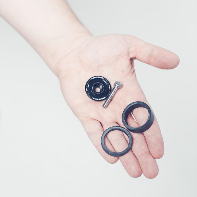
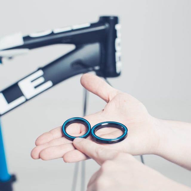
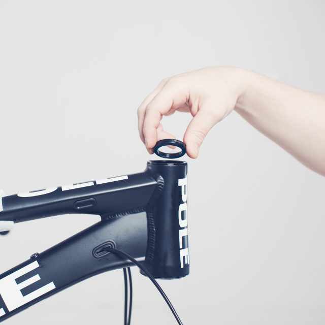
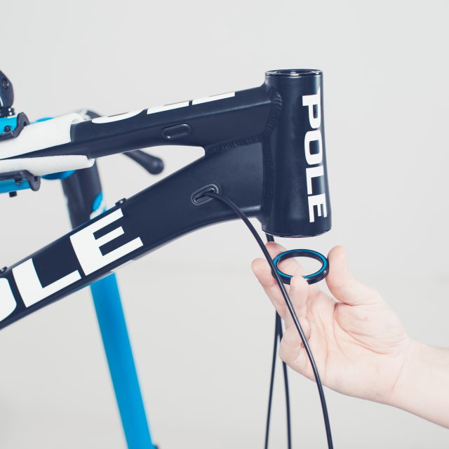
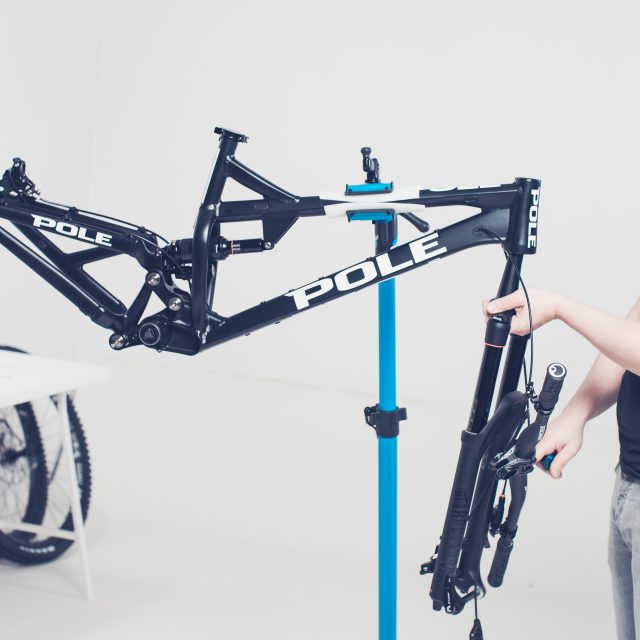
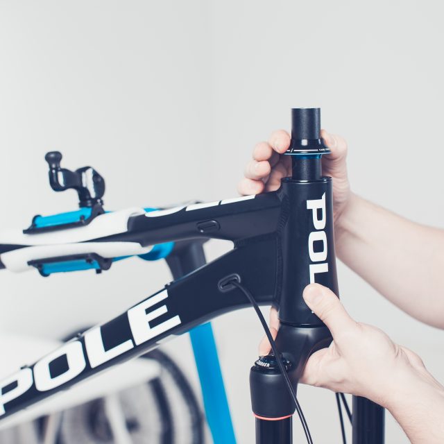
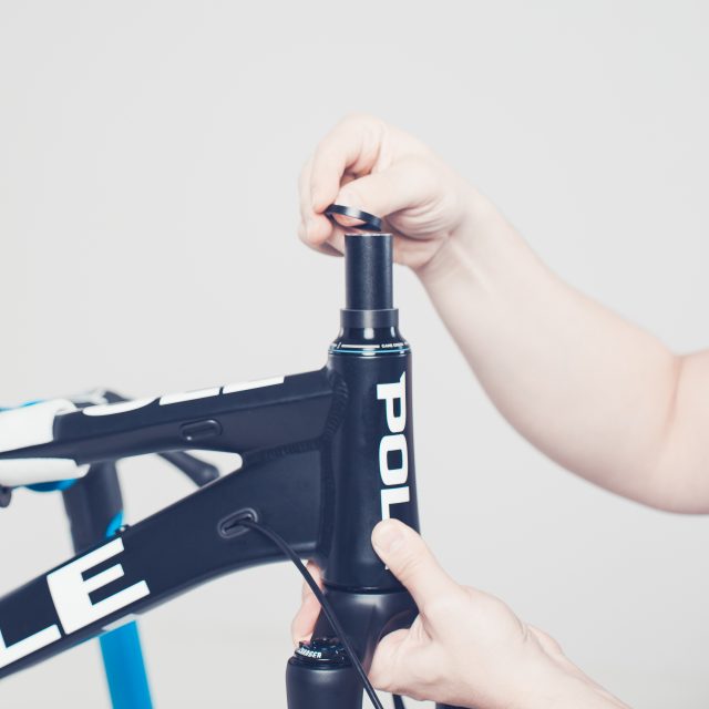
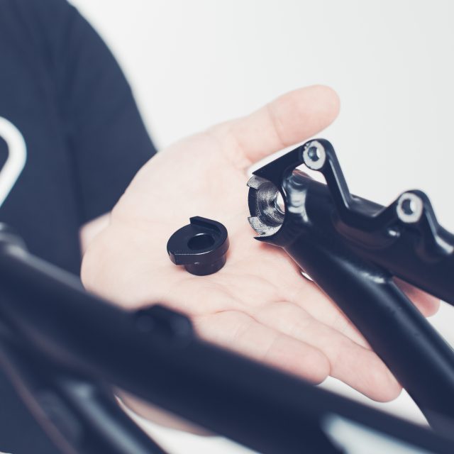
1. For the fork installation, you’ll need the fork and the headset bearings. You’ll find the bearings from the small parts carton.2. Remove the top cap and the spacers from the fork.3. Take the two bearings.4. The smaller bearing goes on top. Check that the side of the bearing, which has the ~ 45-degree angle goes downwards. (We have applied grease to the cup at the factory but if it seems to you that there isn’t enough grease, you can add some. Use only water resistant grease which is suitable for bearings here)5. The larger bearing goes on the bottom. Check that the side of the bearing, which has the ~ 45-degree angle goes upwards. The bearing should stay in place with the help of grease. (We have applied grease to the cup at the factory but if it seems to you that there isn’t enough grease, you can add some. Use only water resistant grease which is suitable for bearings here)6. Now take the for and slide it into the headtube. Check that the cables coming to the handlebar goes neatly on both sides of the fork so you don’t need to redo the cabling. 7. This part needs you to have the rest of the headset parts nearby because you need to hold the fork in place with your other hand. Take the headset bearing cap and slide to the steerer tube. You can add some grease to the o-ring if it doesn’t seem to slide down easily.8. Next, add some spacers. This is your preference. If you use fewer spacers your handlebar comes lower and your driving position at the same time goes forward. But this is something you can adjust later…9. Install the handlebar stem combination.10. And finally, screw the top cap on the place. Now you can let go of the fork. NOTE! You only need to tighten the bolt to 1,1 – 1,7 Nm
If you have done the other steps you can skip to the part where the cockpit setup is done.
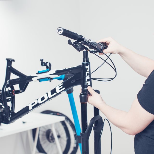
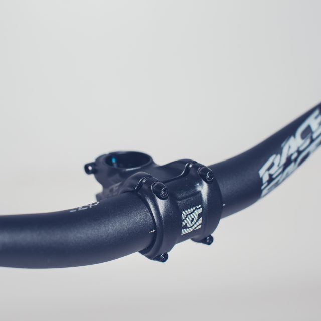
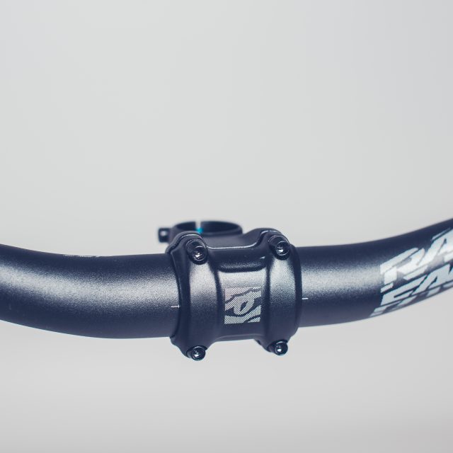
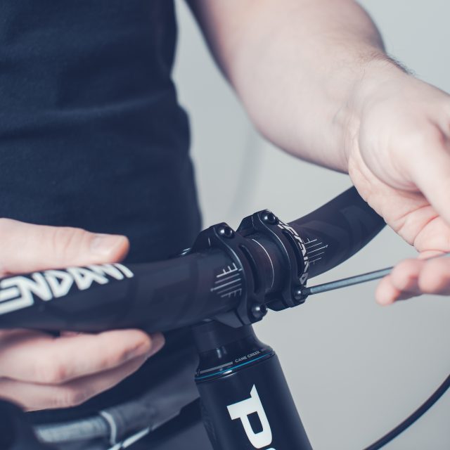
7.Handlebar assembly – Raceface Turbine
Tightening your handlebar to Raceface stem.
The position of the handlebar is driver specific but if you don’t know your preferences we suggest that you’ll install your handlebar so that the horizontal guidance lines in your handlebar are approximately in the middle of the stem’s faceplate. Then you have the manufacturer’s informed amount of rise and backsweep in your use.
You can also follow this link to manufacturers manual.
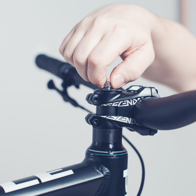
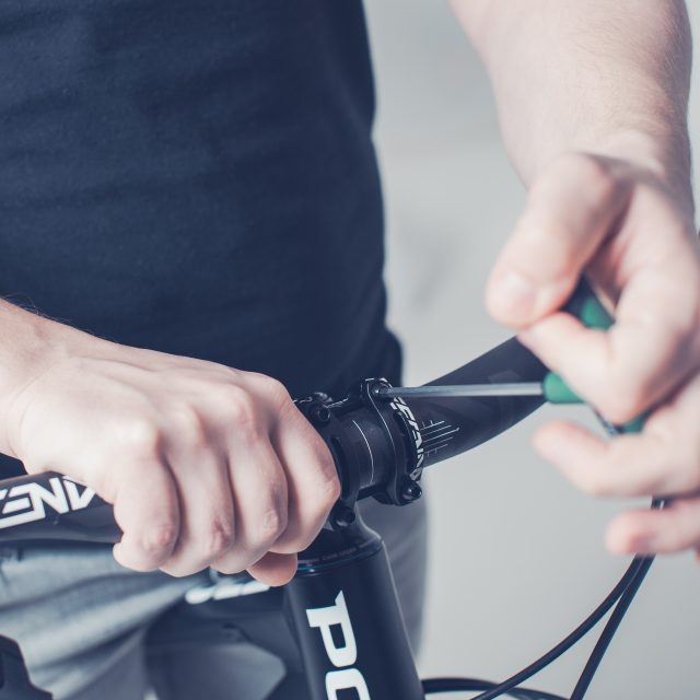
1. First, tighten all the faceplate bolts three rounds clockwise. 2. Measure that the gaps between the faceplate and stem are about the same under each bolt.3. Adjust your handlebar straight before tightening. Start tightening from the left upper corner and go across to right lower corner. Then move to right upper corner and from there to left lower corner. Make an “X” when you are tightening. First tighten the each bolt approx one round at the time and after two or three rounds take a torque wrench and tighten each bolt in “X” pattern to 5Nm
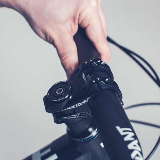
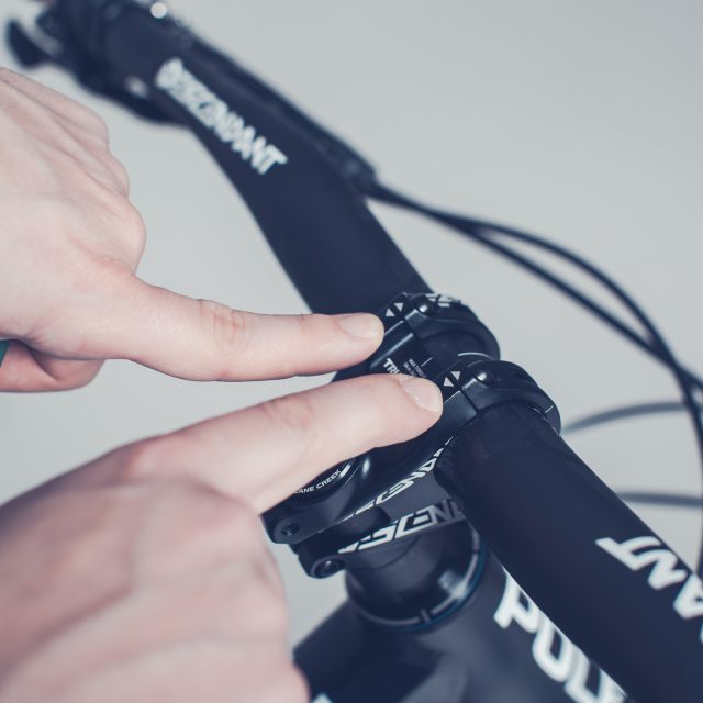
Descentant stem is a little bit different than “regular” stems. The stem has this called zero cap tightening feature.
1. Notice the triangles under upper bolts. That gap is the zero gap.2. First tighten the upper bolts to 5Nm.3. Notice that the gap sould be 0mm after tightening.4. After you have tightened the upper bolts tighten the lowers to 5Nm.
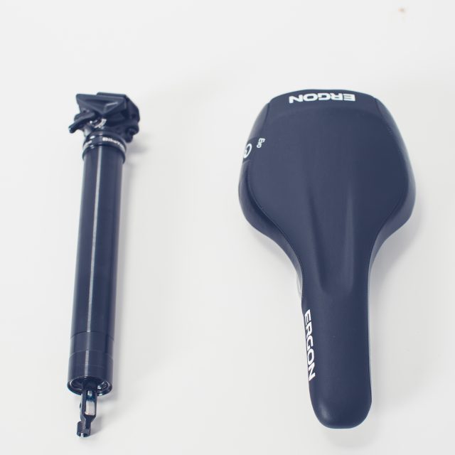
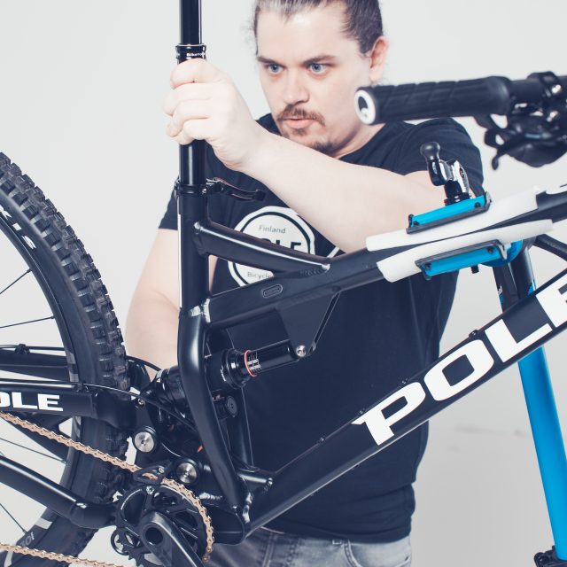
9.Seatpost and saddle installation
It doesn’t matter in which order you make the assembly.
We start by installing the dropper post first.
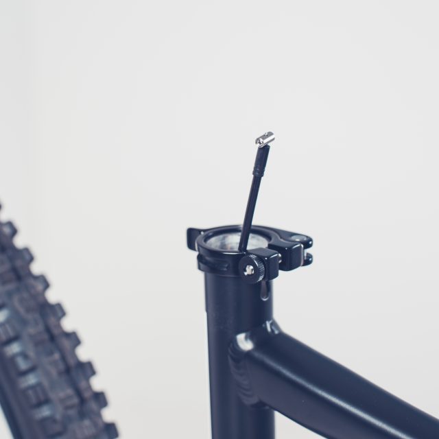
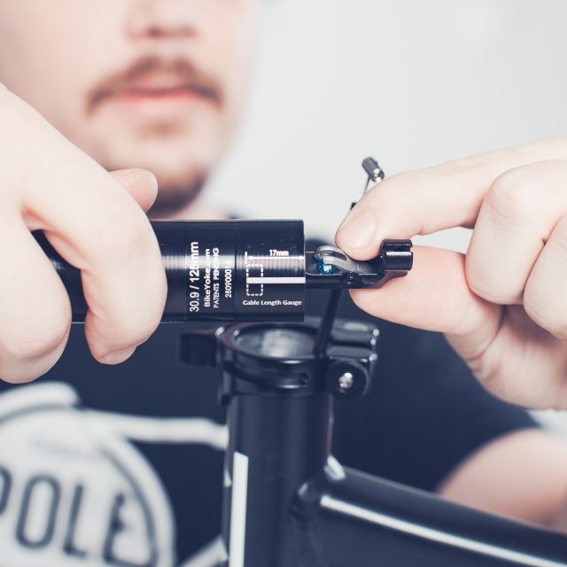
1. Pull the end of the dropper post cable from inside the seat tube visible about 5-7cm.
Turn your handlebar to the right so that it feeds the cable housing towards the rear of the bike. Help by pushing the cable housing into the upper internal cable routing point. At the same time help the cable housing come out from the lower cable routing port. After this pull the cable housing up from the seat tube opening.
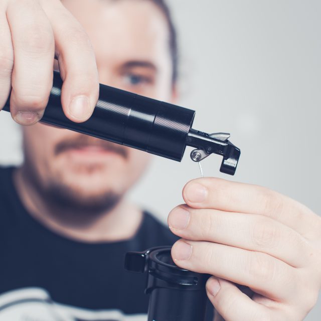
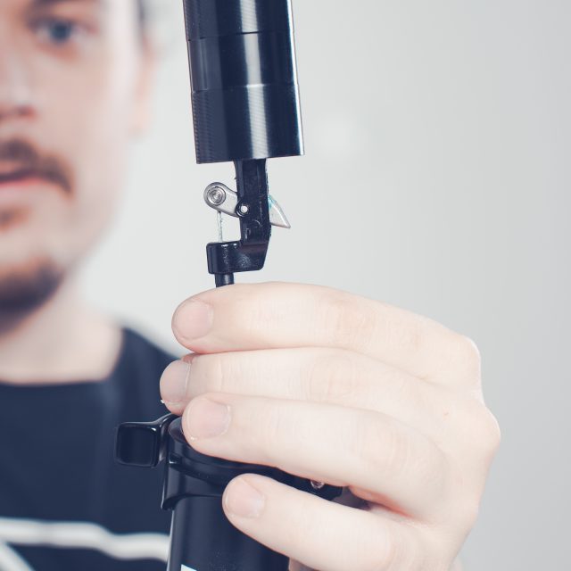
Check that the trigger end of the cable housing is correctly inside the trigger. Check that you have some play in the cable… You should be able to pull the cable approx 17mm visible from the seatpost end.
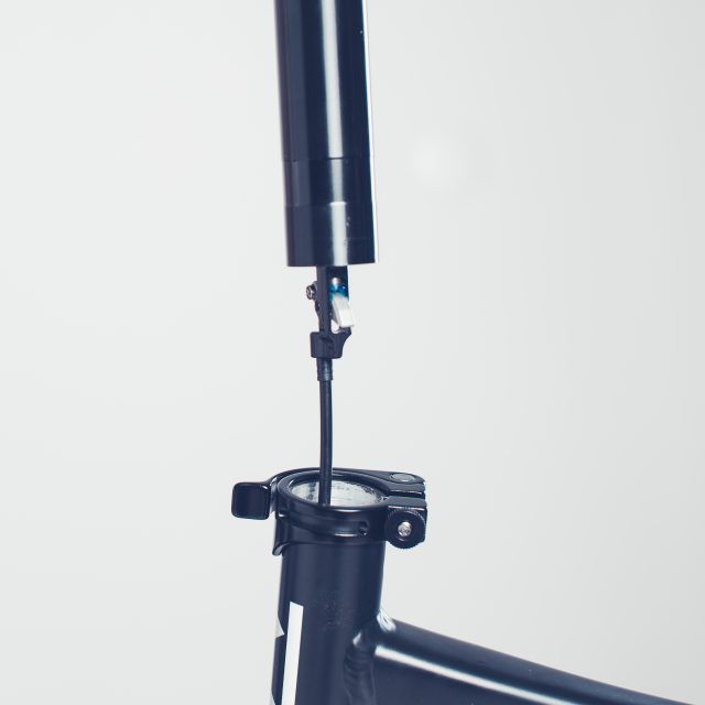
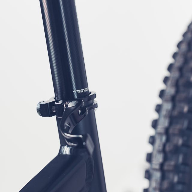
2. NOTE the end of the cable first. There is approx 17mm coming out from the cable housing. Next, you should push the end of the cable into the hole of the end of the dropper post.3. After you have inserted the end of the cable into the hole. Check that the cable goes in the groove so that you are able to turn the post towards the upright position.4. You need to pull the cable a bit harder so that you get the posts mechanism to work. After that, you are able to slide the end of the cable to its place. Now you can test the mechanism and the dropper post by pushing the trigger. If it works and the trigger feels ok, you can slide the post into its place.5. When you slide the post down, help with your other hand by pulling the cable housing from the bottom end of the seat tube. NOTE that if you now pull up from the seat post and the housing is not moving up the same amount you might get the end of the cable housing out from its groove and the mechanism won’t work.6. You need to able to push the seat post so deep into the seat tube that you are not able to see the “minimum insertion” markings in the post. That shows the safety limit that needs to be inserted to withhold drivers weight when driven.
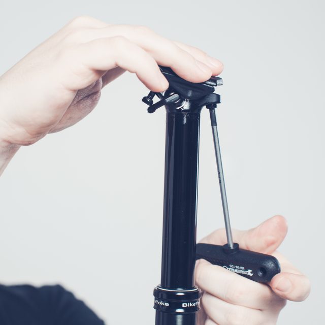
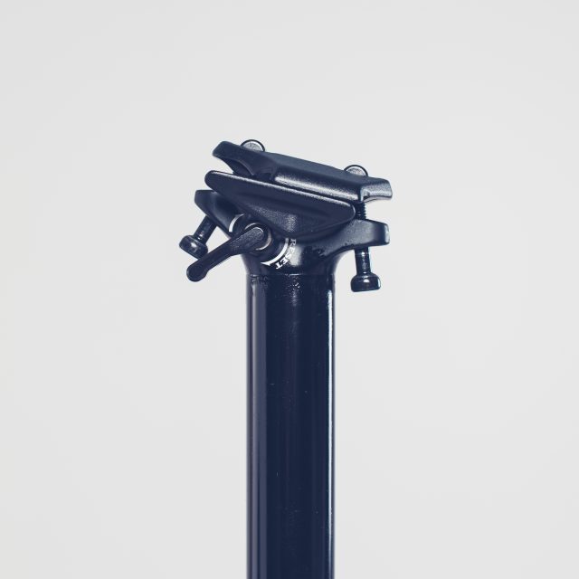
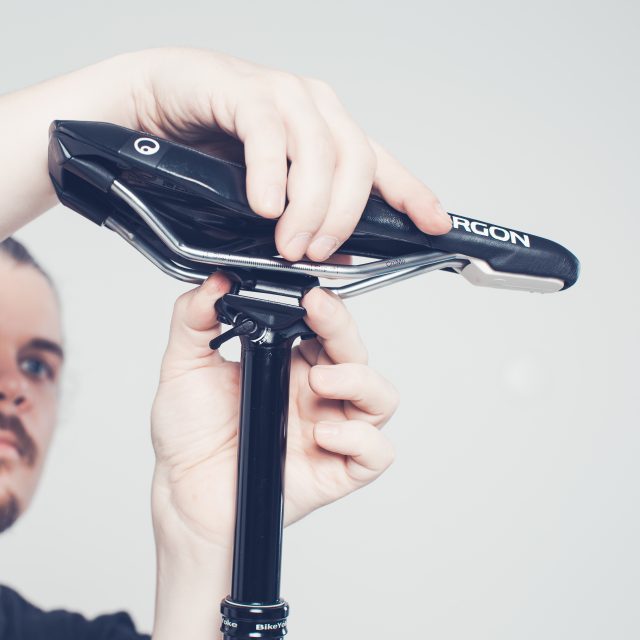
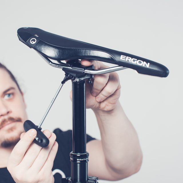
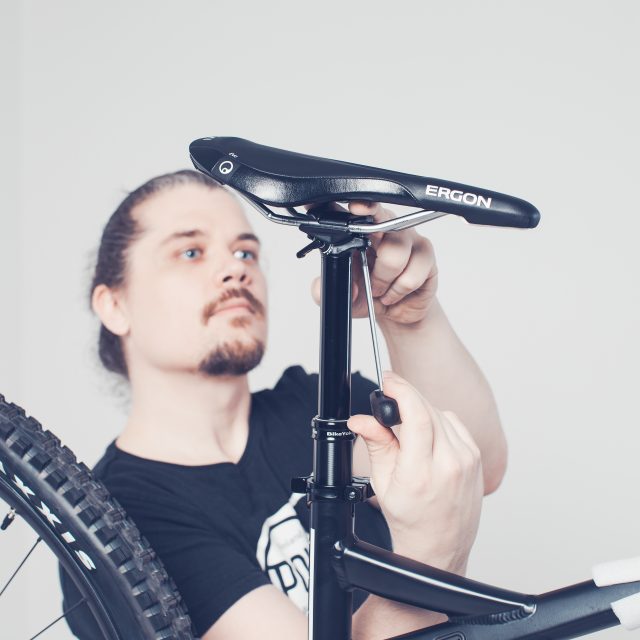
Next we take the saddle and install it.
7. Take Torx T25 and loosen both bolts from the top of the seat post. Loosen the bolts as much as you can without separating those from the “nuts” above.8. Take the saddle on the other hand and with the other hand push the top of the clamping mechanism up so you can slide the saddle on its place. Do one rail first… You need to push the saddle’s rail a little bit over the groove and then you are able to slide the other rail also between the clamping mechanism.9. After you have got both rails in their places you can start tightening the saddle. With your other hand keep the nut in place so it won’t rotate when you tighten the bolt. After few turns, the nut goes into its groove and stays in place. Repeat this to the other bolt.10. Now when you are in the point where you are getting the bolts tightened you notice that now it’s the time to get the saddle in the correct position. We recommend that you tilt your saddle a little bit nose down position. Basically so that after you use your sag the saddle position is almost in level. But at the end, it’s your ass which should feel comfortable when driving so you might to adjust this after few runs.
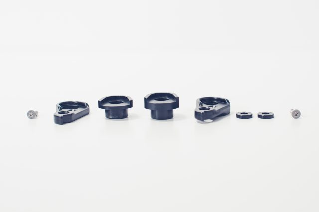
10.Boost vs 142mm standard
Models where availability to change 142 vs 148 standard:
Evolink 2017
Evolink 2018
Taival 2017
Taival 2018
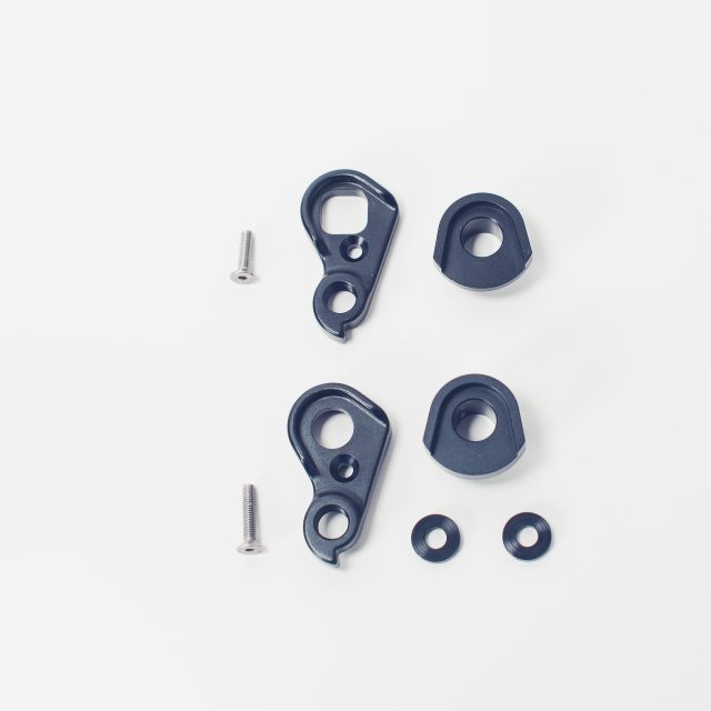
Needed parts for replacement
Below you can see the difference between 142 and 148 standards:
For transforming the stock boost (148mm) standard to 142 mm standard you need to replace the thicker dropouts and add the 3mm spacers to your IS brake mount.
REPLACEMENT
1. Take a flat headed screwdriver and carefully wiggle the left side dropout loose. If it’s not loose already.2. Take a 2mm Allen key and unscrew the bolt from the right side dropout.3. Remove the dropout4. You can see that this is the Boost (148mm) dropout/hanger from the square hole where the axle goes thru.5. For replacing to 142mm standard you need to find this kind of ziplock bag where are all necessary parts for the replacement.6. Find the 142 standard version of the right-hand side dropout and put it in place.7. Take the longer bolt and screw it in its place.8. Use 2mm Allen key the tighten the bolt. Tighten it to 4Nm
9. Find the thicker left-hand side dropout.
10. Install it to its place.11. These spacers go between the frame and the brake caliper.12. Put the spacers first and after this screw the caliper back on.
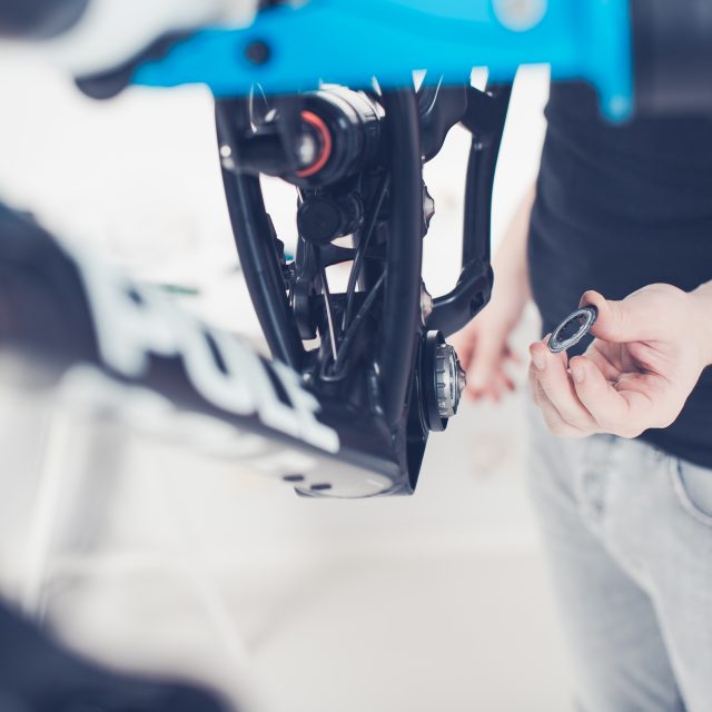
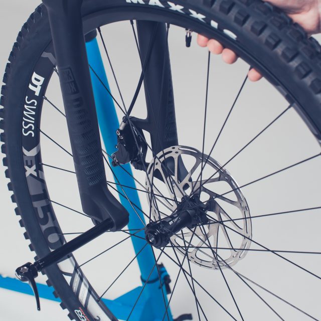
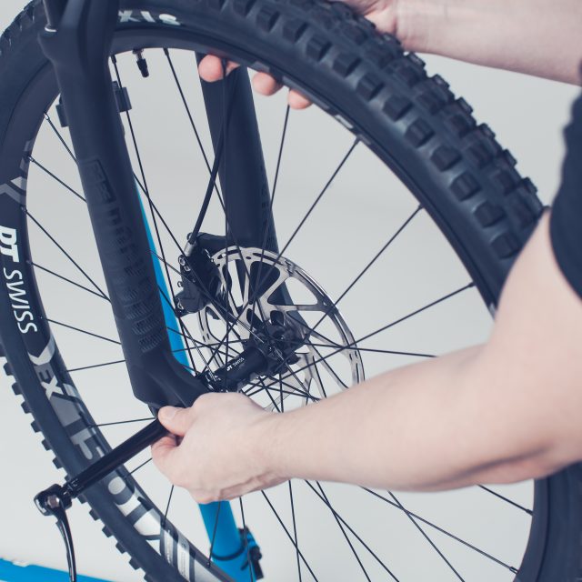
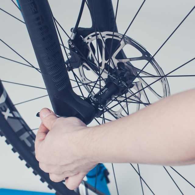
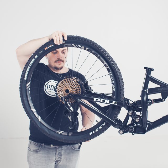
11.Front wheel installation
1. Rotate the front axle off.2. Remove the brake disc adapter3. Install the wheel. Check the brake disc clearance when you install the wheel. Disc needs to go between the brake pads cleanly.4. With these new forks, which are suitable for torque caps, the hub won’t be pressed to the bottom of the hub slot. So you need to line the wheel so that the axle goes thru the hub.5. You don’t have to tighten the axle by screwing it tight. Stop the screwing when the axles clamp is pointing down. Turn the clamp up and it should tighten the axle. Rockshox axles are adjustable, if you need to adjust the axle so that it would work as planned, please review the manufacturers manual page 15.
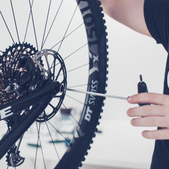
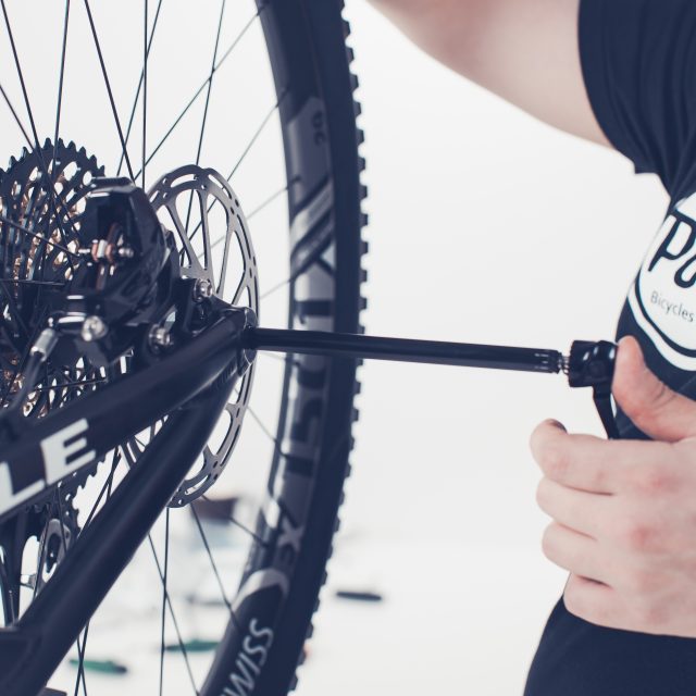
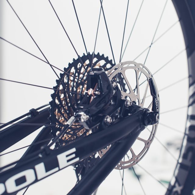
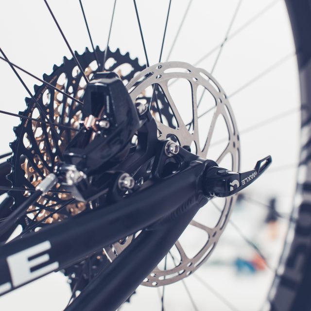
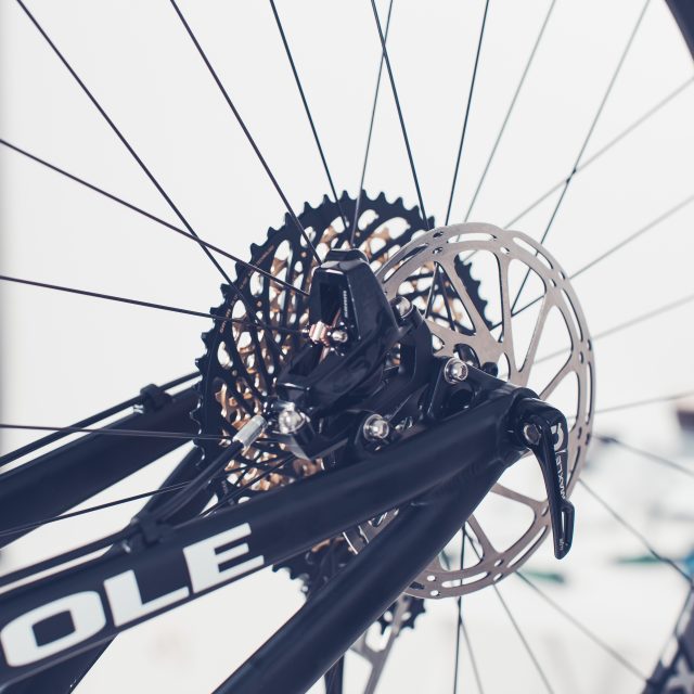
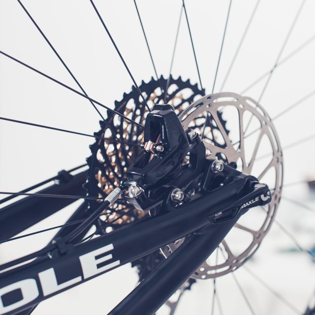
12.Rear Wheel installation
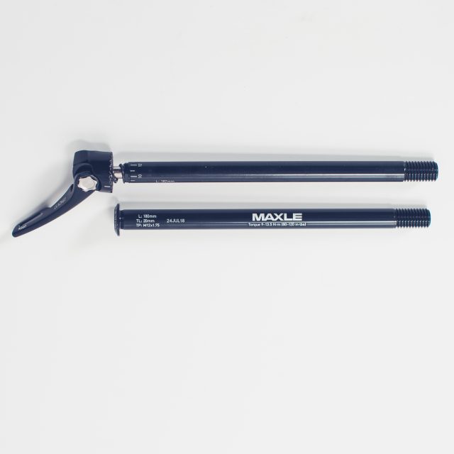
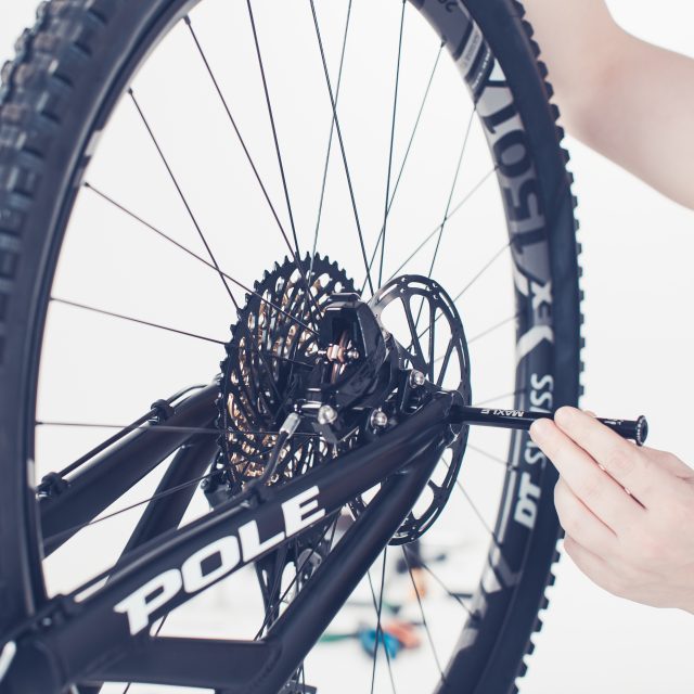
1. Remove the brake disc adapter.2. Install the wheel. The rear wheel doesn’t go in its place if you try to put it vertically. You need to push it a little bit diagonally in place.3. Check the brake disc clearance when you install the wheel. Disc needs to go between the brake pads cleanly.4. For the rear axle, we are delivering two options. Above, Maxle Ultimate and below Maxle Stealth.5. Maxle Stealth. Install the axle when you see that the hub is aligned with the dropouts.6. With Maxle Stealth axle, you need 5mm Allen key. Tighten the axle to 9-13,5Nm7. Maxle Ultimate. Install the axle when you see that the hub is aligned with the dropouts.8. You don’t have to tighten the axle by screwing it tight. Stop the screwing when the axles clamp is pointing down. Turn the clamp up and it should tighten the axle. Rockshox axles are adjustable, if you need to adjust the axle so that it would work as planned, please review the manufacturer’s manual page 15.9. The rear axle you can install so that the clamp is pointing backward when closed.10. Towards down is not good. If something hits the axle you might loosen it.11. Towards forward is not good. If Something grabs the clamp it will open it and loosen the axle.
After installing the axle, you can check that the wheel is fitted tightly by keeping hold of the frame and with the other hand move the wheel to find out if there is any play on the hub.
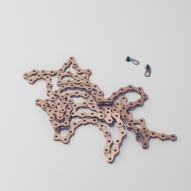
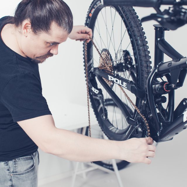
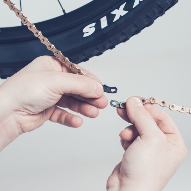
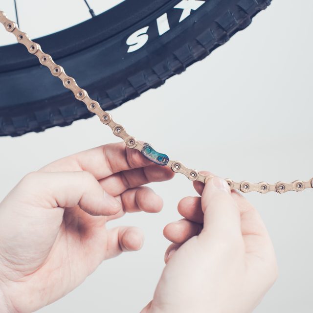
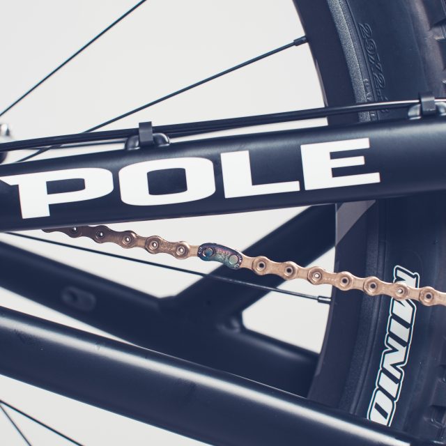
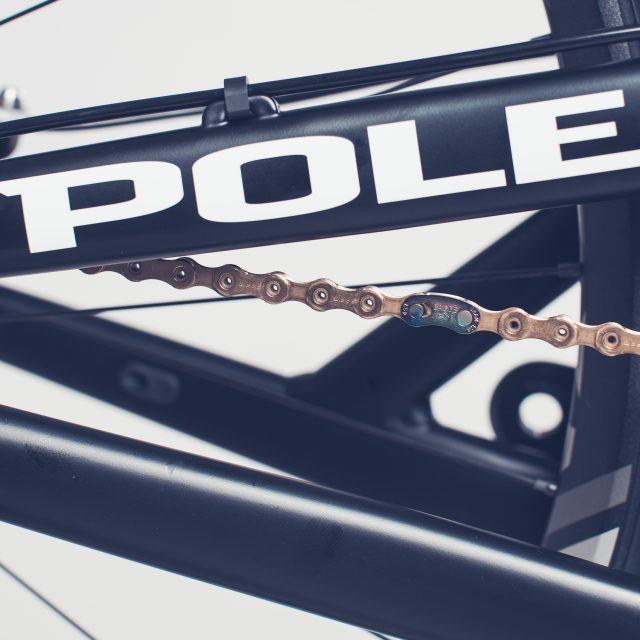
13.Chain installation
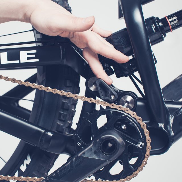
1. You can use this manual with all SRAM chains which has an PowerLock® chain connector.2. String the chain thru between the seat stay and chain stay. Slide it on to correct tooth on the chainring.3. Push the rear derailleurs cage far forward and push the button where you can see the lock sign. That activates the cage lock and helps you to install the chain.4. Slide the chain between the two pullies. But note that the chain goes logically5. Install the chain connector so that the outer curved part of the connector shows outwards.6. Link the chain connector parts together and try to pull the separate to lock them a little bit.7. Rotate the chain lock to the upper side by pedaling carefully so that the lock won’t open when it goes thru the derailleur.8. Forcefully hit the crankarm to pedaling direction with your hand to lock the connector.9. Close and check the chain guide that there is enough room for the chain. If not add or remove the spacers one by one.
If you have problems with the chain installation you seek help form the manufacturers manual.


