If you want to tune or just check the condition of the linkage bearings please follow these instructions. Most of the next steps you can find from the Machine and Evolink BB frame bearing replacement manual with photos.
Tools needed:
Torque wrench with Allen key adapter
For Machine, you need 5mm and 6mm Allen keys
For older Evolink you need two 5mm Allen keys and for updated version 5mm and 6mm Allen keys
Step by step disassembly:
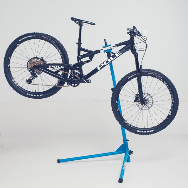
Install your bike to a bike stand
Remove front and rear wheels
Install brake disc adapters to calipers so you won’t press brake pistons too far out.
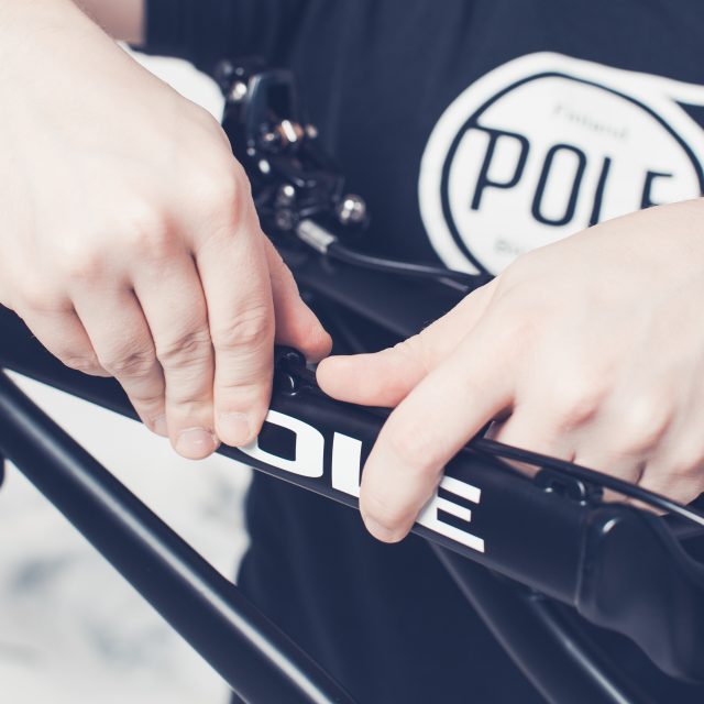
Remove shift and brake cable attachments from the swingarm.
Remove rear shock rear axle
Be careful, the swingarm will drop and you might damage the frame surface (paint or raw).
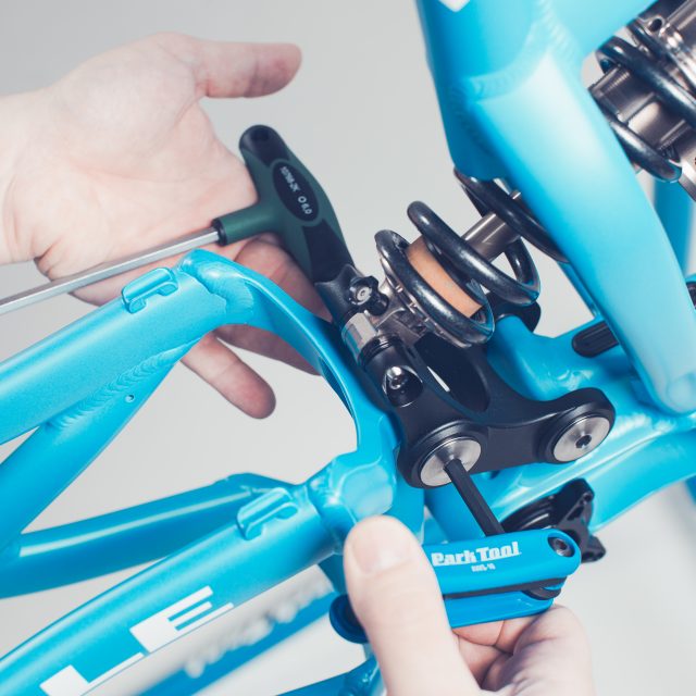
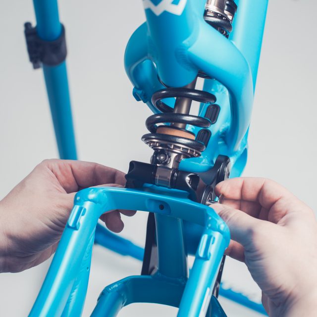
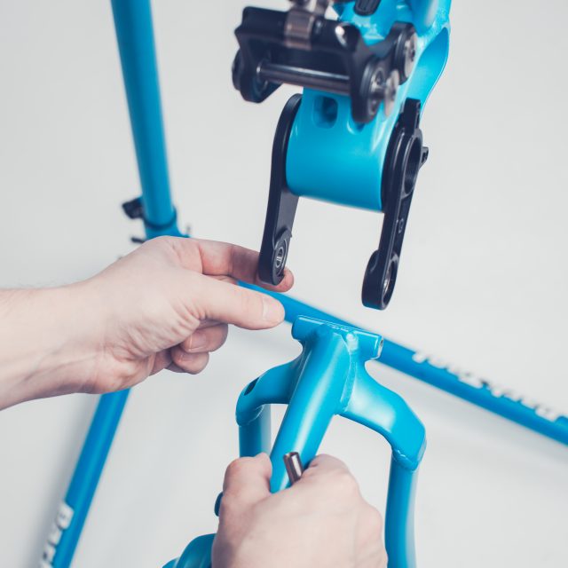
Remove upper linkage rear axle
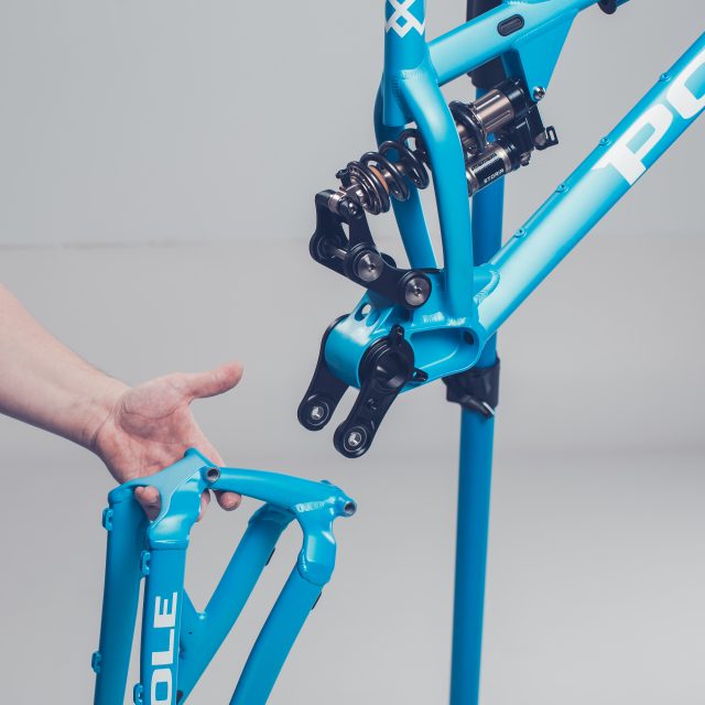
After removing the axle, you can carefully fold the swingarm so that the rear axle is pointing straight down.
Check that the shift and brake cable won’t get dangled or damaged when folding the swingarm. If seems to be too tight to fold, remove rear derailleur from the hanger and brake caliper from the frame.
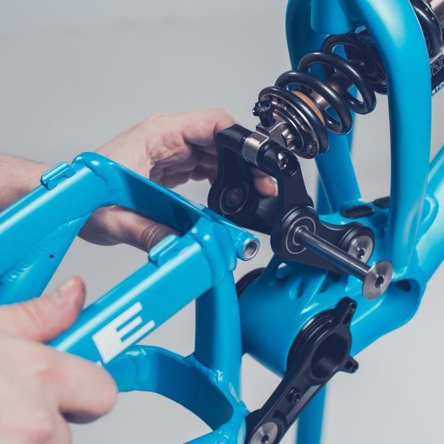
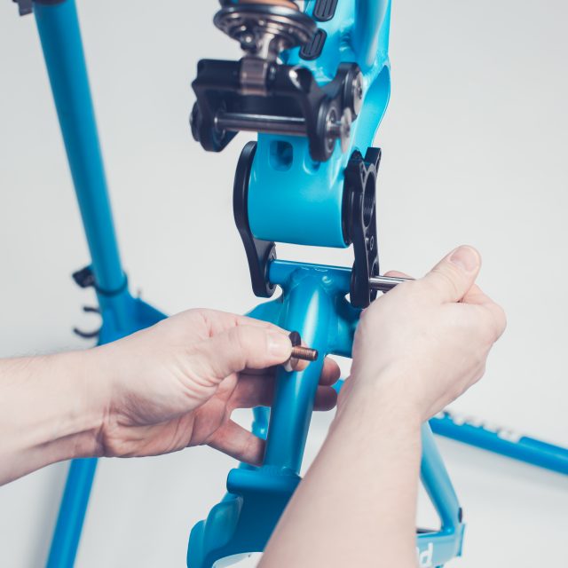
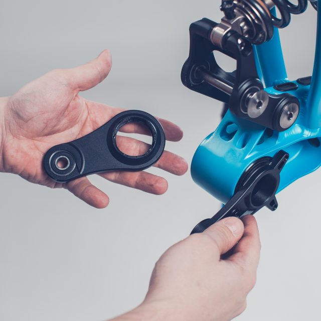
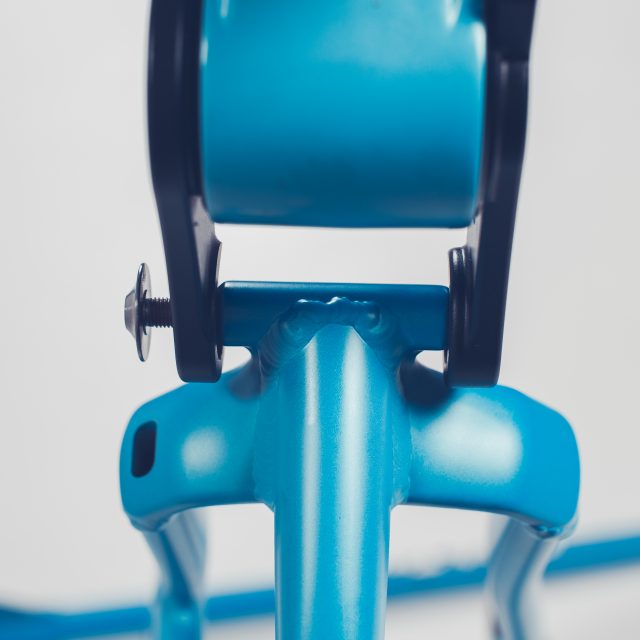
Remove upper linkage front axle
Slide the linkage straight towards the rear of the bike. You should be able to slide it out without damaging the bearings.
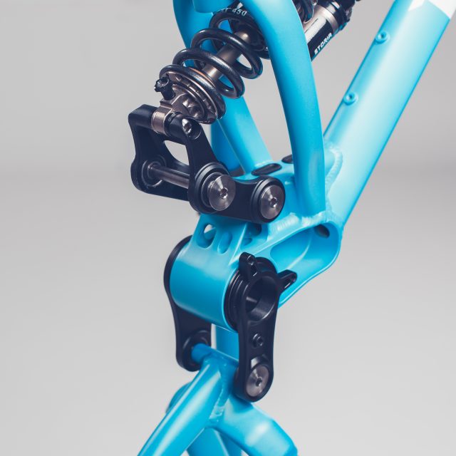
Now the swingarm is only attached to lower linkage.
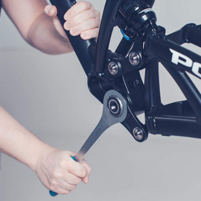
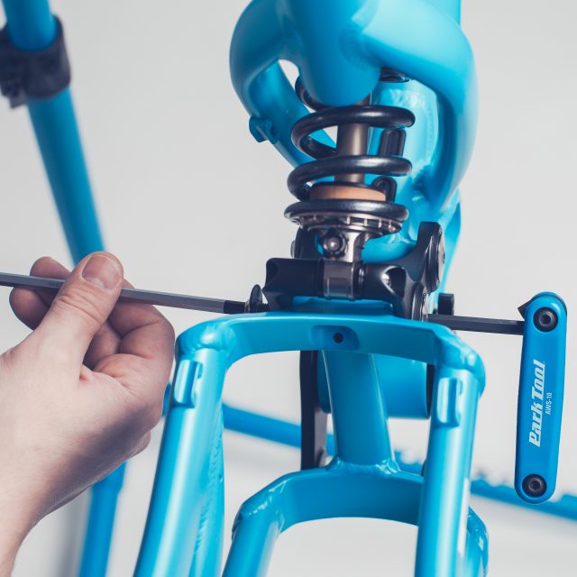
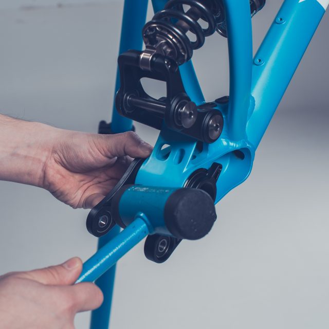
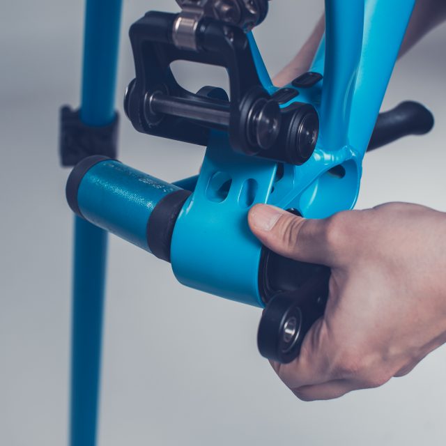
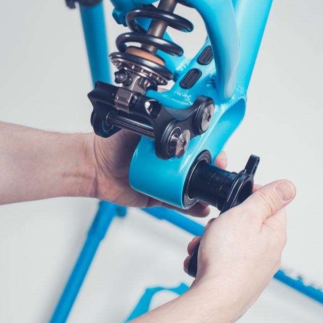
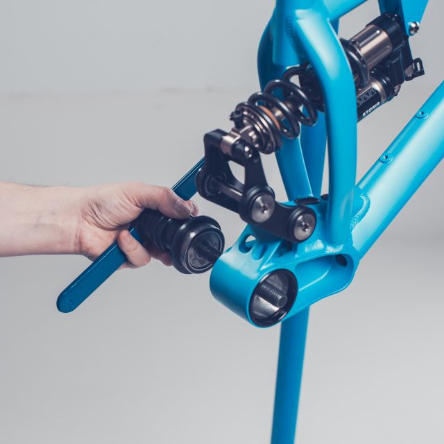
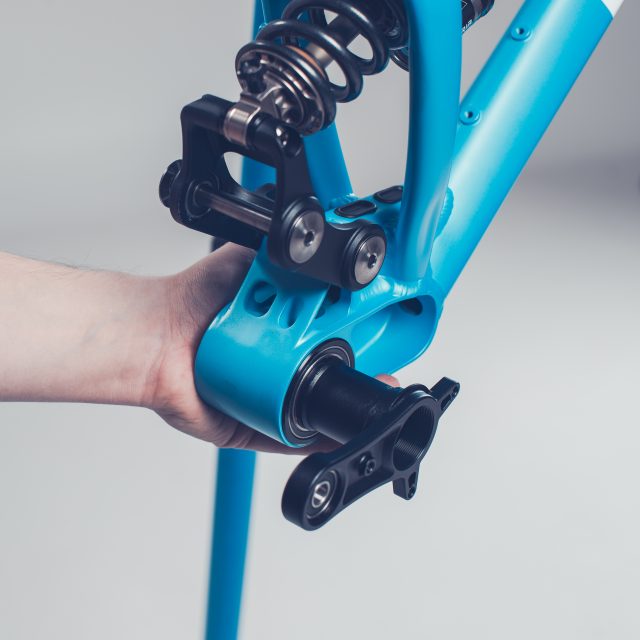
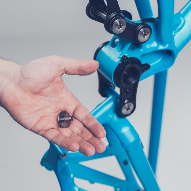
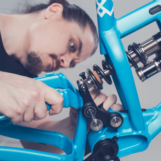
Remove the lower linkage axle.
Now the swingarm is loosely hanging between the linkage
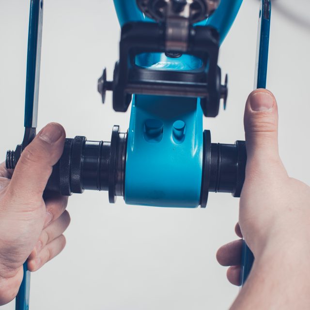
Hold the swingarm in place and at the same time turn the linkage counterclockwise. You should be able to slide the swingarm free without damaging the bearings.
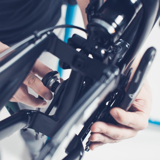
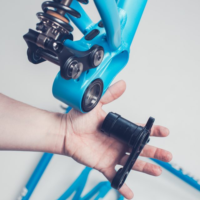
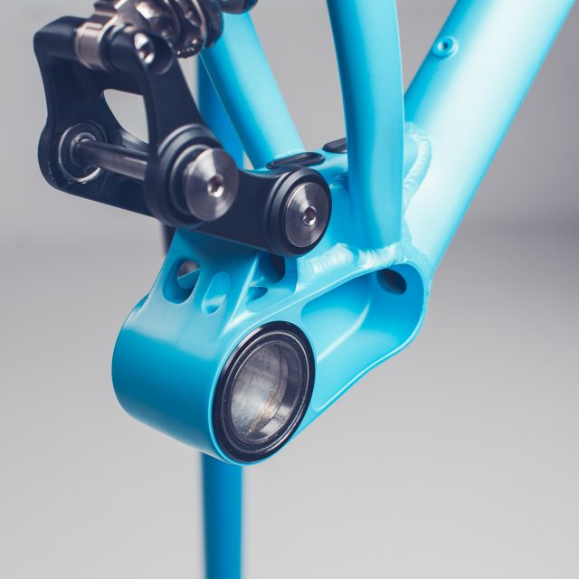
Now you are able to check and clean all the linkage bearings. If you want to regrease the bearings you can do it from the one side only without unmounting the bearings. If you find out that there is something wrong with the bearing, usually it’s a hail mary fix to regrease the bearing. You might get some mileage out from it won’t fix the already occurred problem.
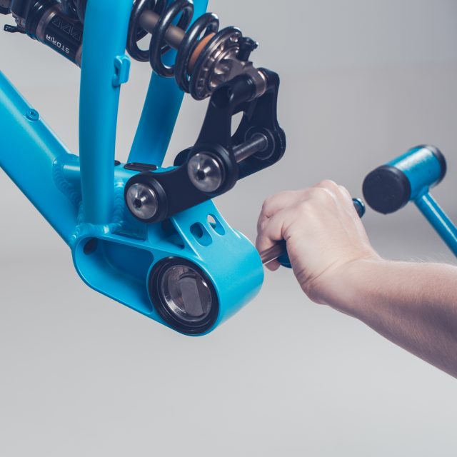
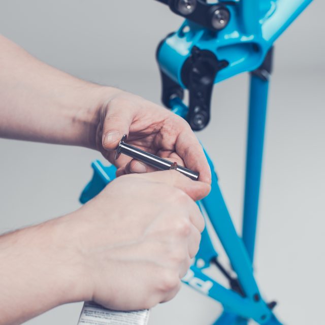
Step by step assembly:
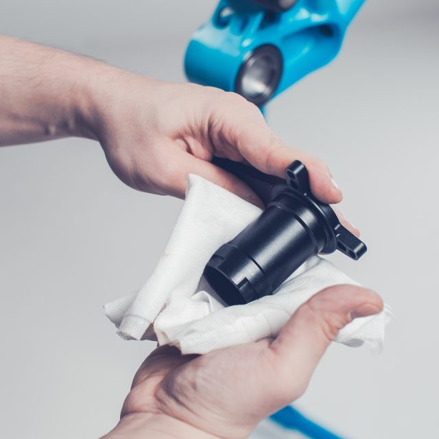
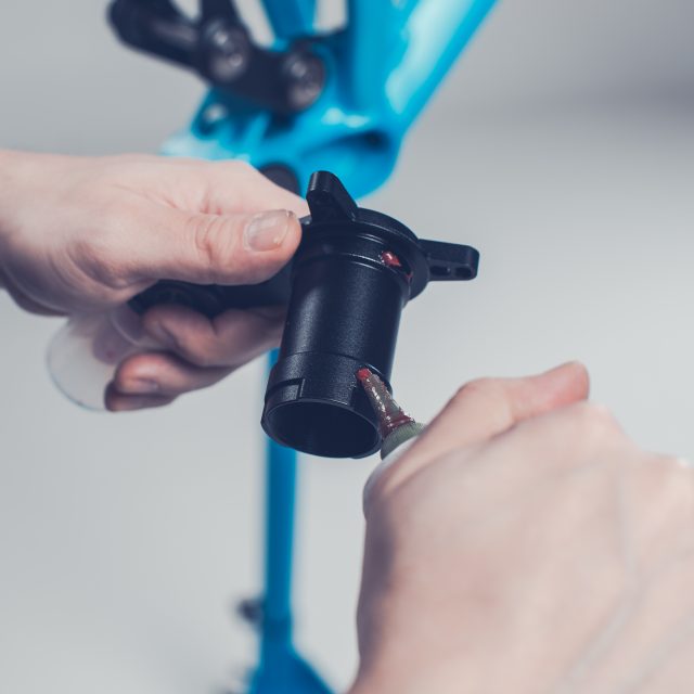
Clean all titanium axles and regrease the axles with low friction and water resistant grease.
Do not use an excessive amount of grease, a thin film won’t gather too much dirt.
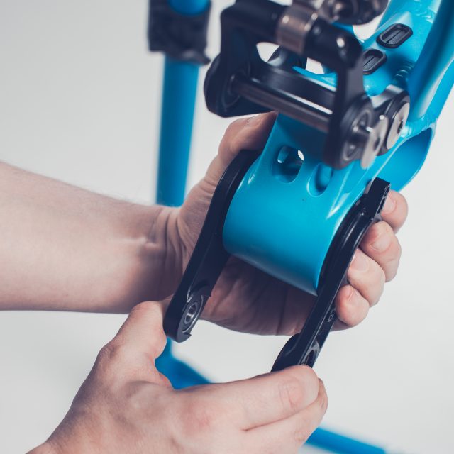
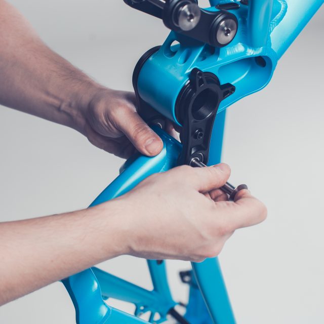
Install the upper linkage.
Start by sliding the upper linkage so that you are able to install the front axle. Be careful not to harm the bearings seals.
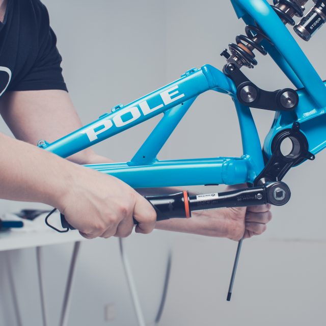
Slide the axle and install the bolt. (Tightening torque is 20Nm)
Attach the rear shock to the upper linkage.
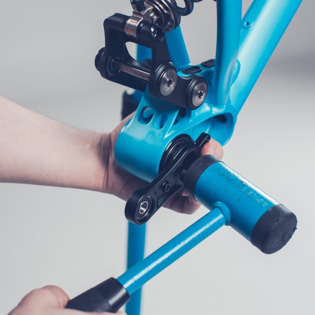
Slide the axle with the washer and install the bolt. (Tightening torque is 15Nm)
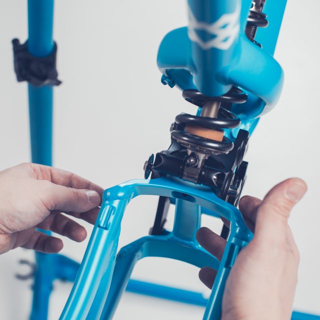
Slide the swingarm between the lower linkage carefully by pushing the lower linkage axle holes towards the front of the bike.
Notice that the shift and brake cable should be above the axle. If you haven’t removed the brake caliper and the rear derailleur it might be a bit tricky to get the swing arm in place.
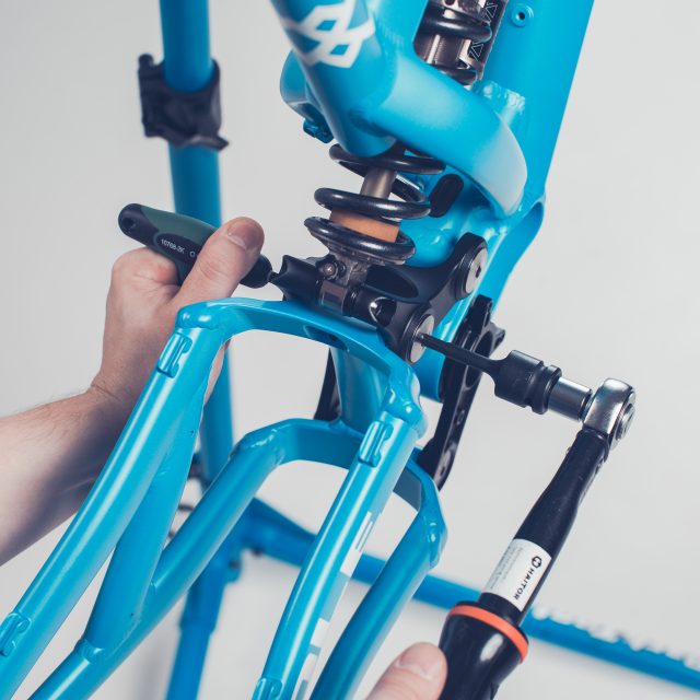
Slide the axle and install the bolt. (Tightening torque is 20Nm)
Turn the swingarm on the correct position.
Level the swingarm axle hole with the bearings
Slide the axle and install the bolt. (Tightening torque is 20Nm)
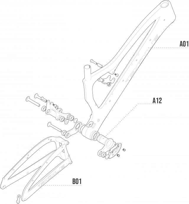
There is a disassembly picture in the next manual. From there you are able to find the correct installation directions for the axles, if you forgot it during the disassembly.
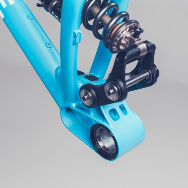
2.Machine and Evolink linkage bearing replacement
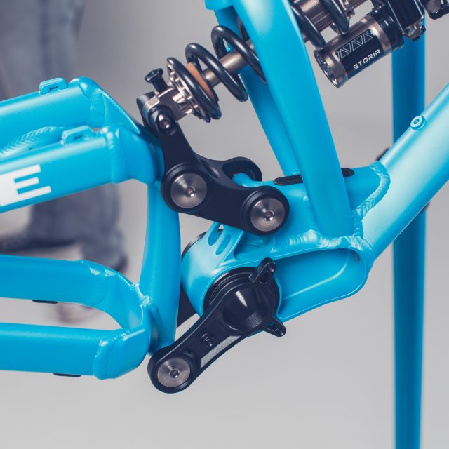
1. Here you can see how the whole frame disassembles. This picture can be used with Machine and Evolink frames.
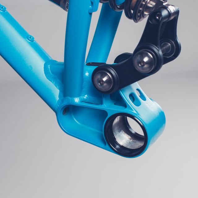
3.Machine and Evolink BB frame bearing replacement
You can use this manual if you want to check or replace the bottom bracket cup bearings. This manual works both, Machine and Evolink frames.
Before beginning the service we recommend that you wash your bike as good as you can.
1. After the bike is washed, install it to the bike stand.
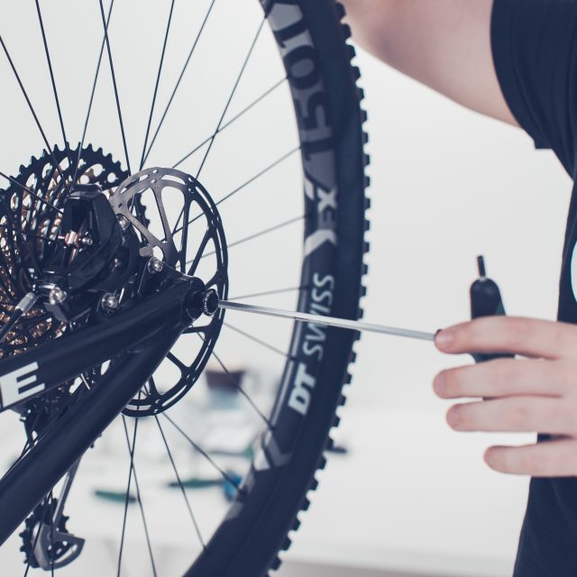
2. Remove the rear wheel. If you have Maxle Stealth rear axle you need 5mm Allen key.
2. Remove the rear wheel. If you have Maxle Ultimate you just open the mechanism and turn the axle open.
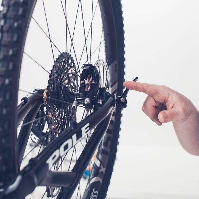
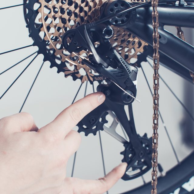
3. Push the rear derailleur cage towards the front of the bike and push the lock button which pointed by the index finger.
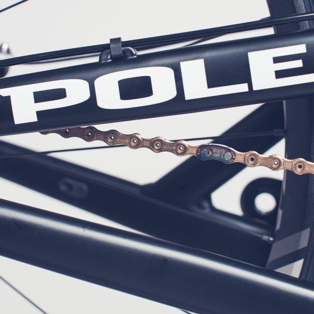
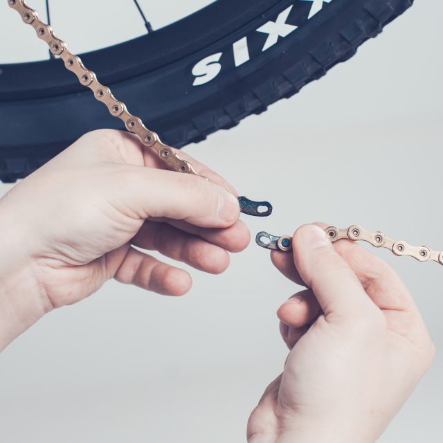
4. Look for the chain connector/master link. Use the master link pliers to open the chain connector as seen in the next photo.
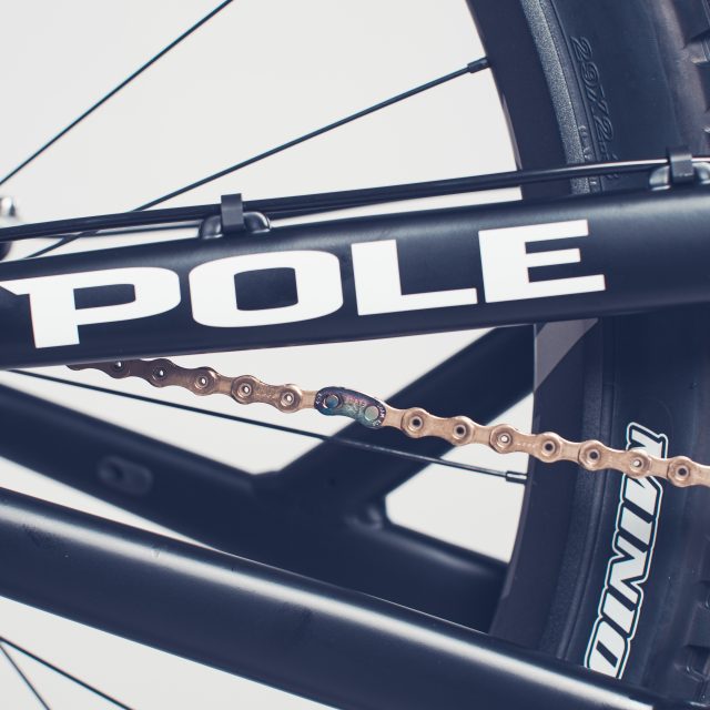
5. Chain connector/Master link open
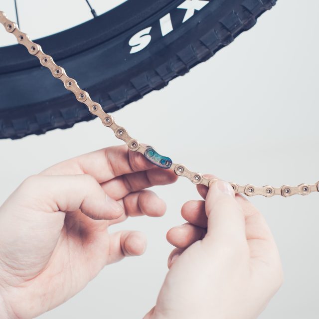
6. Twidle the chain a bit and you should be able to release to chain connector.
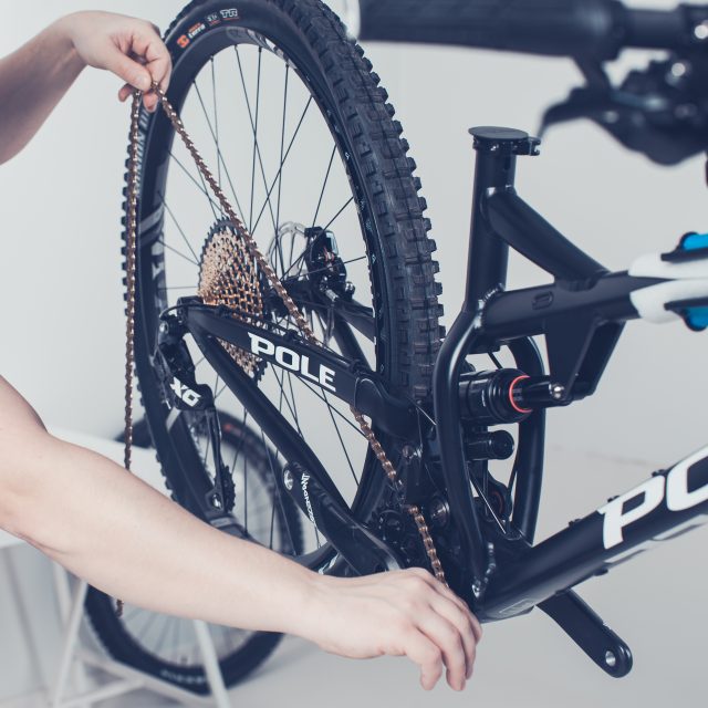
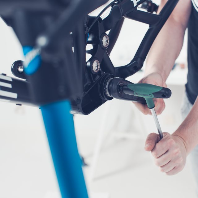
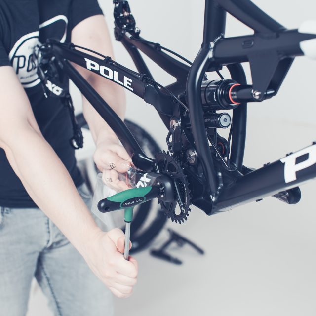
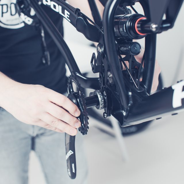
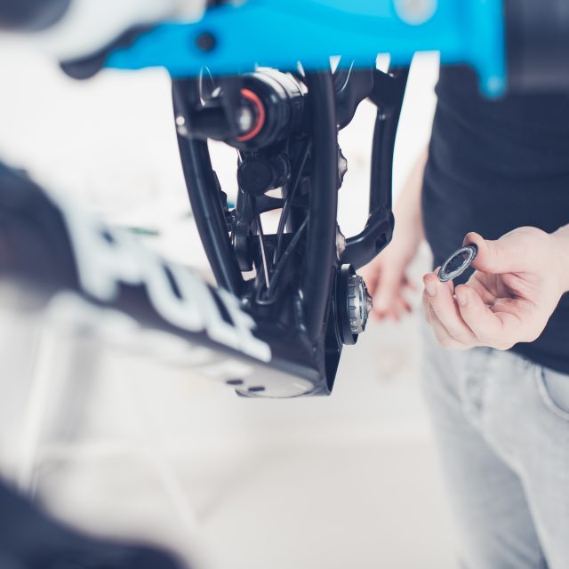
7. Remove the chain8. Use 8mm Allen key to open the crankset. If you have a GXP bottom bracket the bolt is at the non-drive side and if you are using DUB or RaceFace bottom bracket the bolt is at the drive side.9. Crankset bolt in the DUB crankset.10. After completely loosening the bolt. The crank from the loosened bolt side (GXP=non-drive side, DUB=drive side) should come off easily11. Now you should be able to slide the crank with the spindle/axle out from the bottom bracket. In many cases, you need to give it a gentle but firm hit with the rubber ended hammer to loosen it.
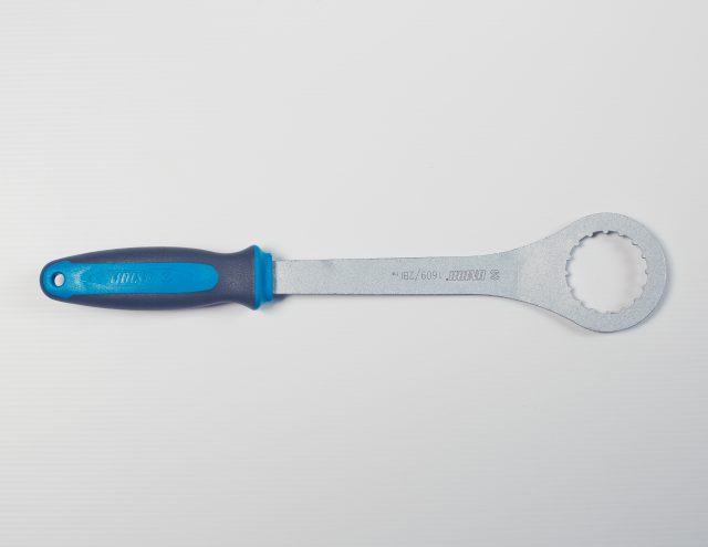
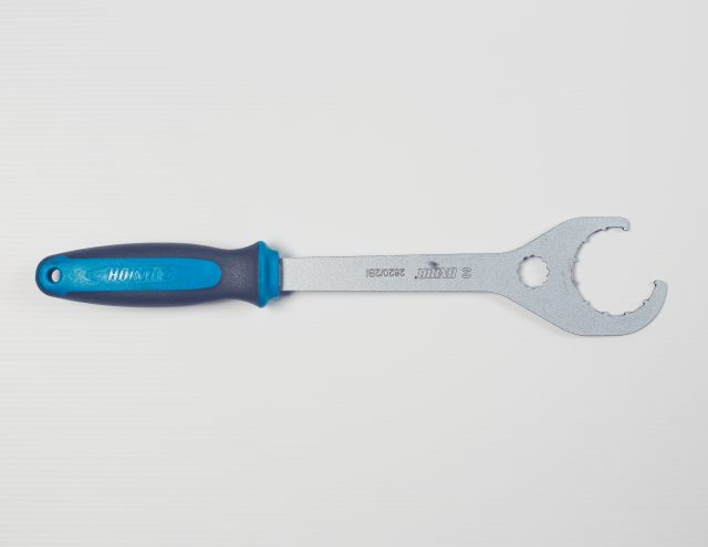
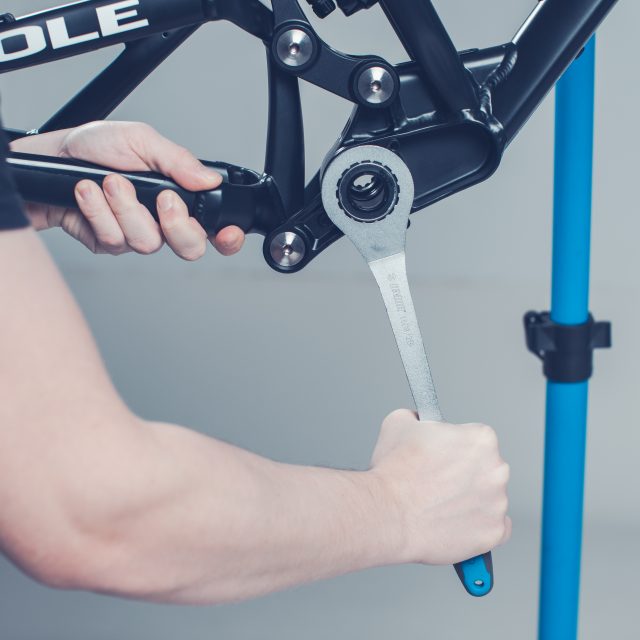
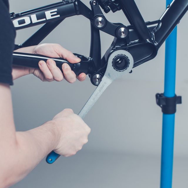
FOR THE NEXT STEP YOU NEED A SPECIAL BOTTOM BRACKET TOOL
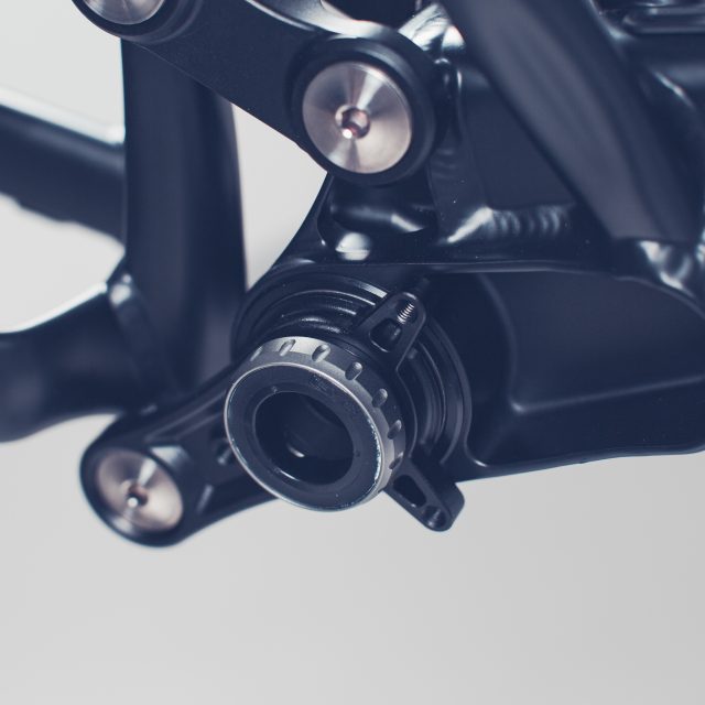
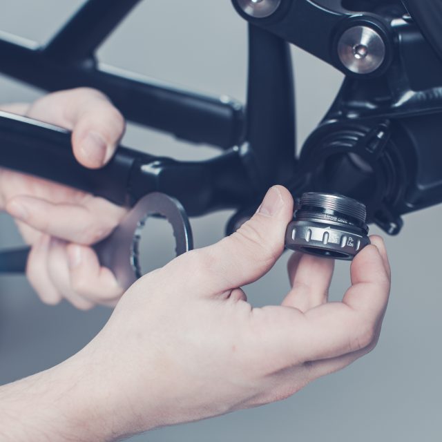
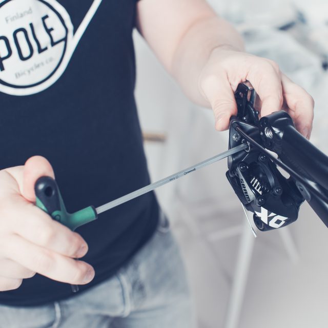
For GXPFor DUB/RaceFace12. GXP BB has this metallic dust ring which easily goes missing, so take it in safe at first. You might find it from you crank also. After this remove the bottom bracket.NOTE the drive side bearing has a left-handed thread so for removing the bearing you need to turn clockwise (This works on all bottom brackets which can be installed on Pole frames).13. To open drive-side BB you need to turn the bearing clockwise.14. Note that there is a spacer under the cup between the frame and the bearing.15. The non-drive side bb opens like normal bolt, so just turn counterclockwise to open.16. No spacer under the non-drive side bearing.17. Remove the rear derailleur18. Remove the rear brake caliper19. Remove the cable clamps. With Evolink be careful not scratch the frame. There are no good tools for this, we use small flat blade screwdriver for this. With Machine you only need to cut the zip ties with wire cutters.20. Now you have taken the bottom bracket off from the both sides21. Open the upper linkage swingarm axle. For Evolink you need 2x6mm Allen keys and for Machine you need 5mm and 6mm Allen keys. For the next batch of axles, Evolink will be updated also for 5mm and 6mm Allen keys.22. After loosening the axle, remove the bolt.23. Remove the axle. If the axle is stuck screw the bolt back few threads and hit it with rubber ended hammer few times for loosening the axle.24. After sliding the axle out you can carefully slide the swing arm out. Swingarm slides towards the end of the bike, not down.
When you fold the frame, watch the cables for the rear caliper and rear derailleur.
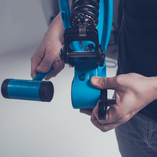
25. Now the swingarm should hang free26. Loosen the lower linkage axle. For Evolink you need 2x6mm Allen keys and for Machine you need 5mm and 6mm Allen keys. For the next batch of axles, Evolink will be updated also for 5mm and 6mm Allen keys.27. Remove the bolt and slide the axle off.28. Slide the swingarm of from the linkage. If your linkage points down, you should turn the linkage counterclockwisee or push the swingarm towards the front of the bike to release it.29. Tap the non drive side link with the rubber ended hammer and it should come loose.30. Tap the non-drive side link from the drive side.31. Keep tapping the link until you are able to free the link from the non-drive side bearing.32. Now wiggle and pull and turn and twist the link so that you get it freed from the drive side bearing33. View from the drive side34. View from the non-drive side. Notice that the bearing is deeper into the cup than drive side.
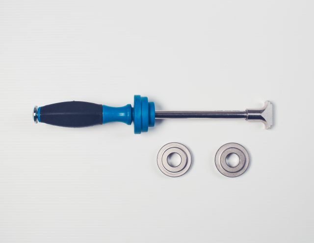
FOR REMOVING THE BEARINGS WE RECOMMEND THAT YOU USE EITHER BOTTOM BRACKET BEARING TOOL SET FROM PARK TOOL OR INNER BEARING PULLER (for inner bearing puller you need the puller for 40mm bearing)
35. I’ll use the Park Tool for this.36. Set the tool so that you only hit the bearing, not the cup. Go around the bearing as long as you need to get the bearing of. Repeat on the opposite side.37. Both bearings removed.
ASSEMBLY
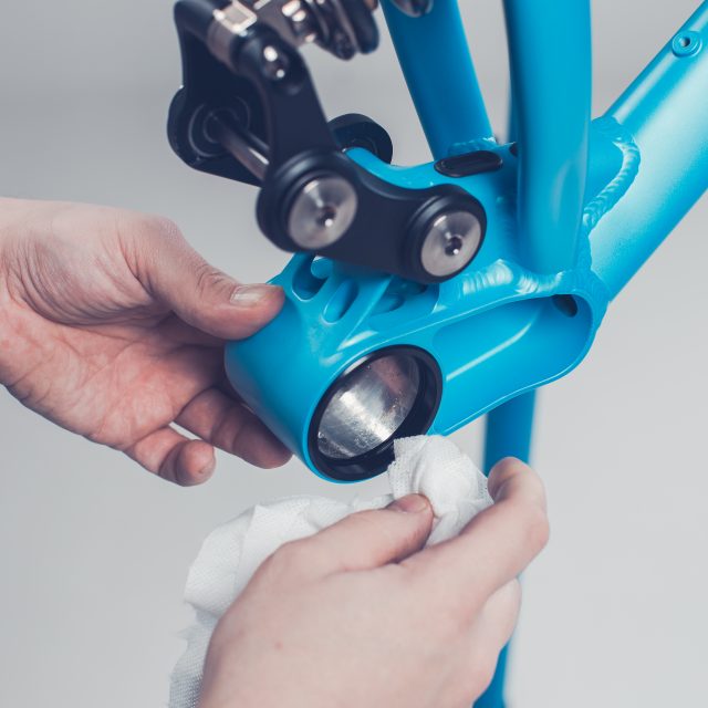
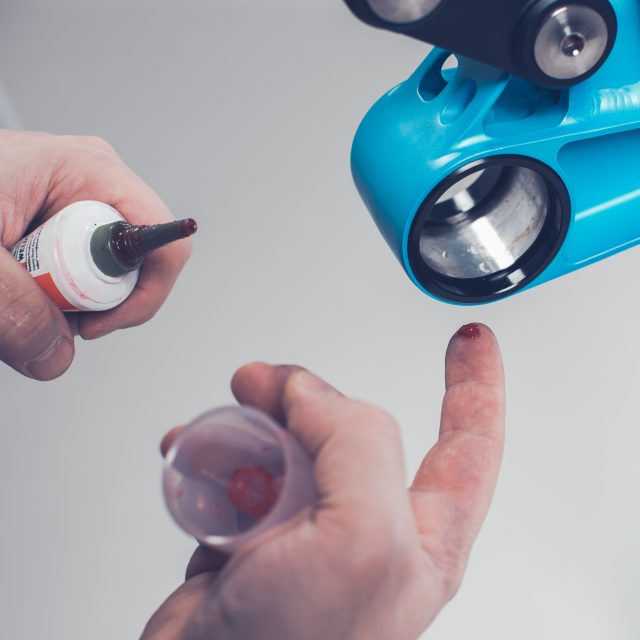
38. Clean the bearing cups and the cup housing with a dry clean cloth. You can use isopropyl alcohol also to remove all dirt and old grease.39. Lubricate the bearing cups. If you use grease, check that the grease is water resistant. You can also use bearing adhesive. This is mainly for avoiding corrosion and easier installation.40. Lubricate both cups.
FOR THE NEXT STEP WE RECOMMEND TO USE SPECIAL TOOL. EASIEST TOOL IS A THREADED BEARING PRESS TOOL.
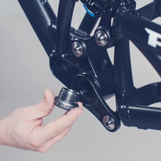
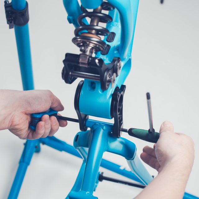
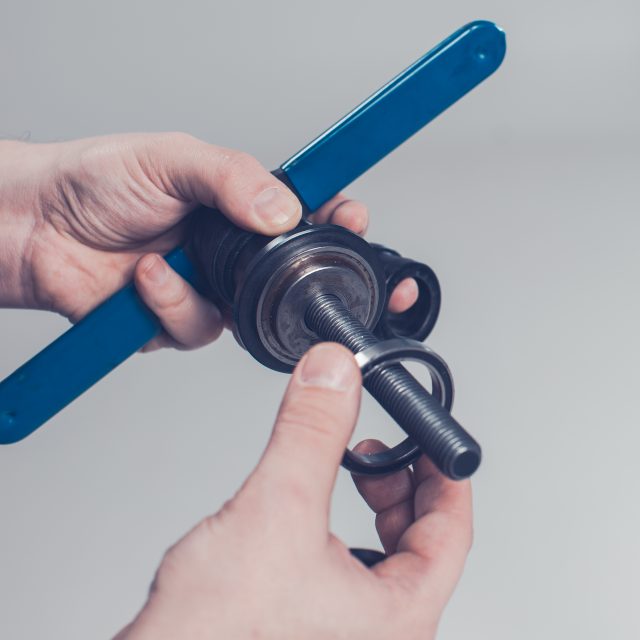
41. Install the bearing to your tool42. Slide the thread thru the bottom bracket shell and…43. Rotate the other handle to the thread until you notice that the bearings starts to insert the cup.44. Follow all the time that you are pushing the bearing straight into the cup. If it starts to go not straight adjust the position of the bearing tool so that you press more from the higher side of the bearing until the bearing is straight again. Keep turning the tool as long as the bearing hits the bottom of the bearing cup. Repeat on the other side.45. Take a clean cloth and wipe the drive side lower linkage clean. You can use isopropyl alcohol or similar to get all ole grease and dirt out.46. Grease the bearing contact surfaces with water resistant and low friction grease. Do not use an excessive amount of grease, a thin film of grease is enough so it won’t gather too much dirt.47. Push the drive side lower linkage thru the first bearing by hand. You might need to push turn and twist the link carefully thru.48. After getting the link thru the first bearing you might need to use a rubber ended hammer to get it thru the second bearing. If you need to use the hammer, you can feel the link align with the two bearings, and when it does align, gently tap the link thru.49. Install the non-drive side lower link next.50. Align linkages and you should be able to push the non-drive side link all the way by hand. If not, use the rubber ended hammer to help you.51. Now you can “hang” the swingarm on its place. Linkage should be so tight fit that the swingarm would stay put between the linkage. But be careful, you might drop the swingarm.52. Take the matching axle and grease it. Use water resistant and low friction grease and apply a thin film.53. Align the swingarm and install the axle.54. Clean the bolt and add either copper paste or similar anti-seize compound.55. Screw the bolt to the axle. You could tighten the bolt at this point but it’s easier after the upper link is also connected to the swingarm.56. Repeat the previous cleaning and lubricating process with the axle. Put the axle “on hold” in the bearing.57. Align the swingarm with the axle and push the axle thru.58. Repeat the anti-seizing process with the bolt and screw the bolt to the axle.59. Tighten both loosen axles with torque wrench and at the same time check the third upper link axle. Torque for the axles is 20Nm.60. Install non-drive side bottom bracket bearing. Note, no spacer on this side.61. Tighten as usually to clockwise direction. Torque for this is 33-41Nm62. Remember the spacer on the drive side bearing. And remember that the thread is left-handed.63. To tighten, rotate to the counterclockwise direction. Tighten to 33-41Nm
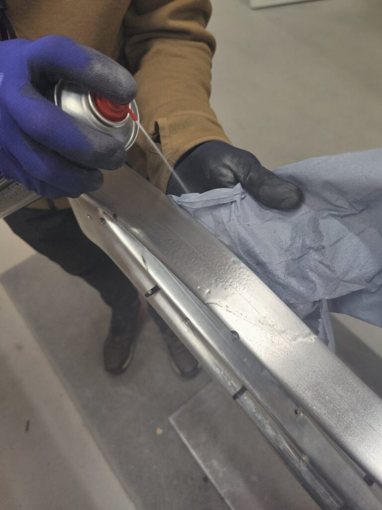
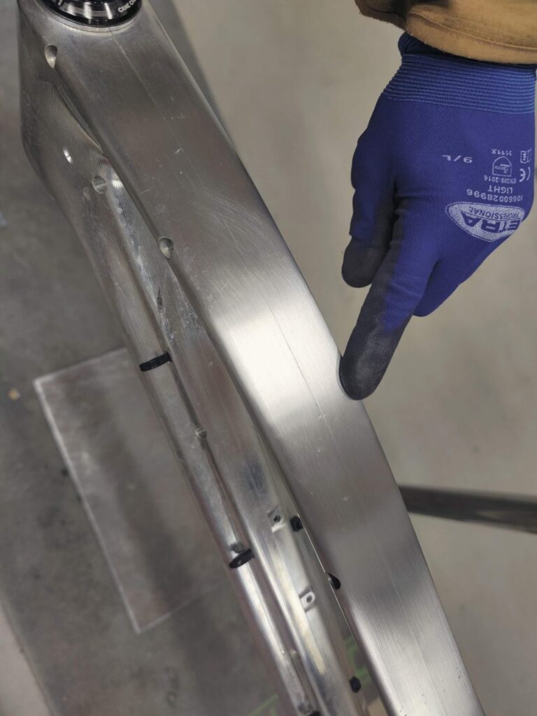
4.Quick guide for oxidation removal from the raw aluminum frame
The Pole Bicycle frames – the Stamina and the Machine – with raw aluminum finishes maintain their appearance best when washed regularly with fresh, sweet water, preferably after every ride. Don’t leave the bike outside in rain or in high humidity overnight or for long periods of time. Store the bike in well ventilated and dry conditions.
Note! Do not consider applying any surface treatment to the frame such as anodizing, powder coat paint, Cerakote, etc. Applying any surface treatment might damage the bonding of the frame which might lead to premature failure not covered by warranty. For example, the acid bath involved in anodizing will have adverse effects on the glue used in the bonding as do the high temperatures that are part of the powder coat process.
Follow the instructions described below to keep your Pole Bicycles frame in good condition. The process described has been developed by ourselves. This is an abrasive method to remove the oxidation. Proceed with caution and remember that you are REMOVING MATERIAL from a thin-walled tube. If you do this often, too large area or remove too much material, you are risking the frame construction. If you don’t know what you are doing, please leave this to professionals. Pole is not responsible for the outcome and THIS OPERATION MIGHT VOID WARRANTY.
List of things you need:
Norton F2504 Beartex Hands Pads or similar
Tissue paper
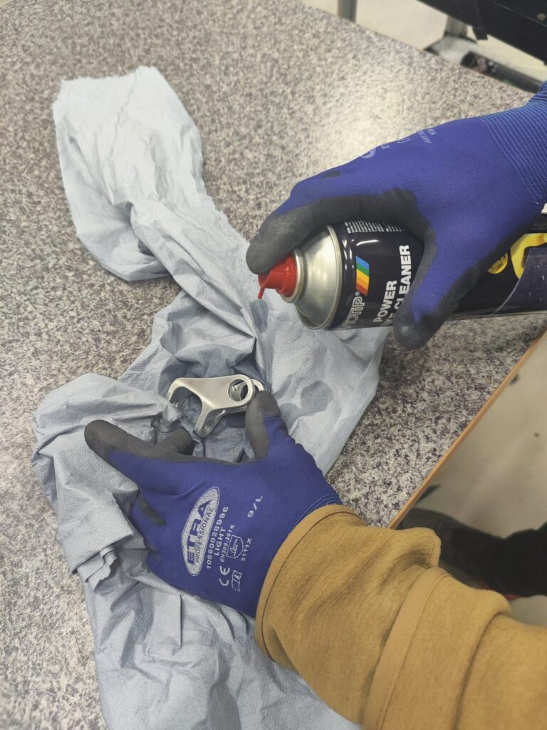
Isopropyl alcohol or brake cleaner
Well ventilated place to work
TIME!
Steps for the project:
For this purpose, disassemble the bike from other parts if needed. It’s best to take out cabling etc, so you can work freely.
Remember to use protective gear (safety glasses and gloves) and do this project in a well-ventilated place.
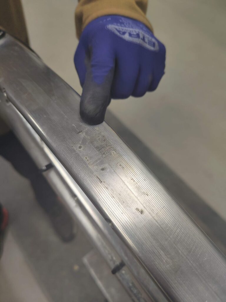
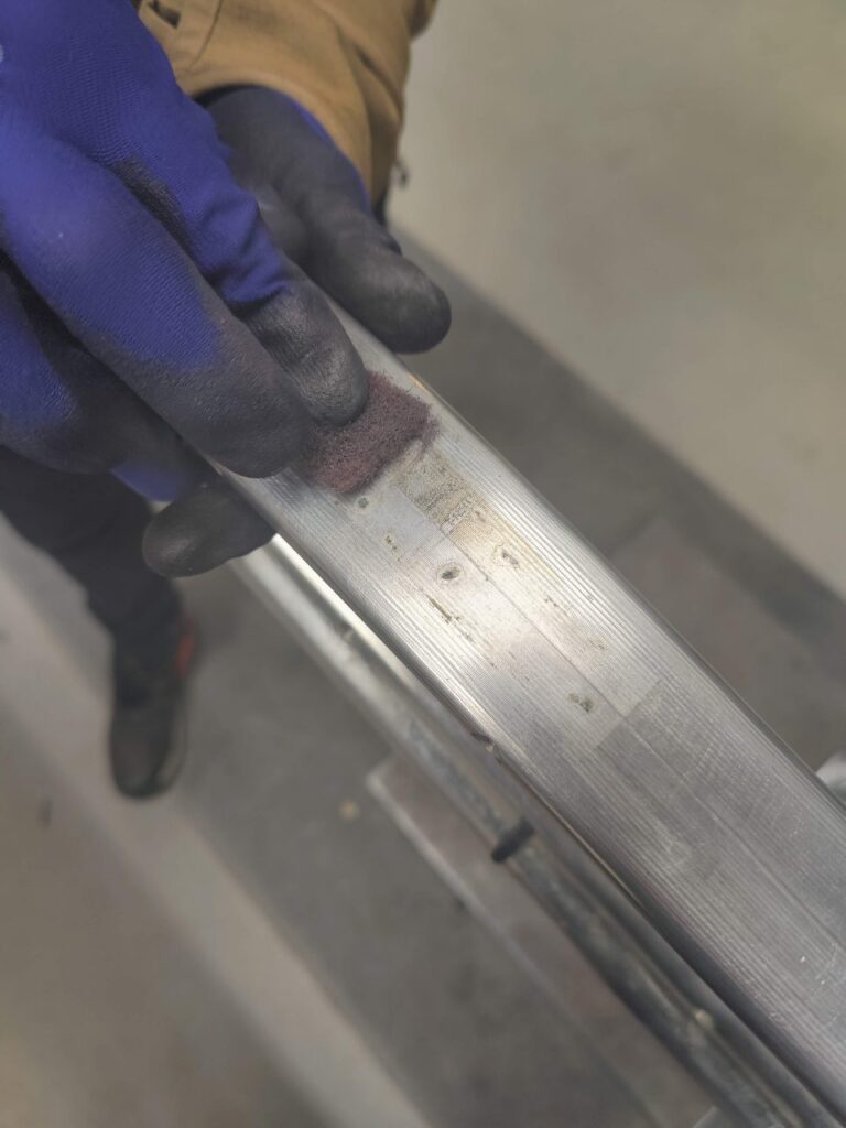
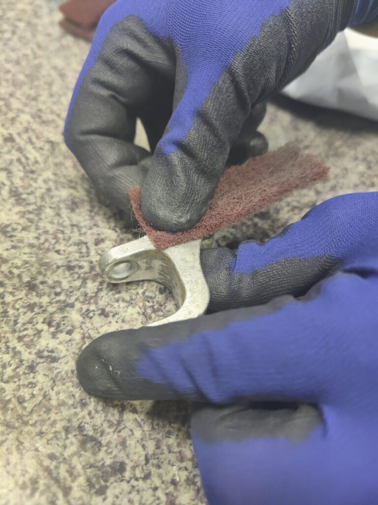
Sand off the corroded spot from the frame with light pressure on the pad.
Feather off some oxidation around the corroded part.
Clean the surface with alcohol and tissues
Wait one week (seven days) until riding the bike.
Things you should not do:
Don’t sand off material too often. Once in the season is ok.
Don’t treat the whole frame
Don’t emove too much material. Just lightly on the surface
Don’t use any machines to do this operation
Don’t do this outside
Don’t do this in high humidity
Don’t touch the frame with bare hands
Don’t use tap water within one week to clean the frame
Don’t ride the frame for one week after doing this
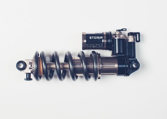
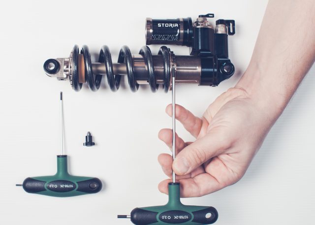
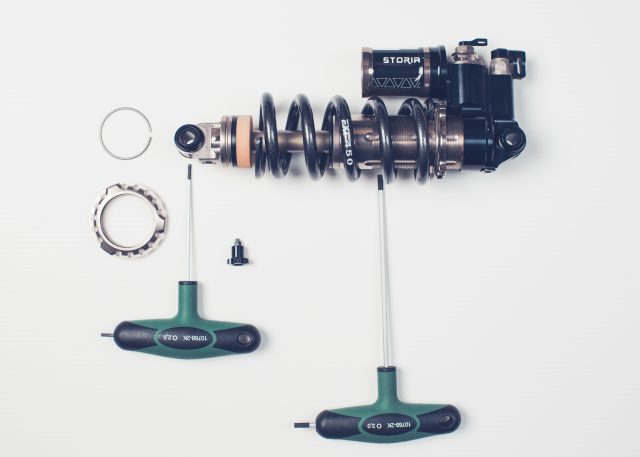
5.EXT Coil replacement
Before disassembly, we recommend that you write down your shock settings (how many clicks from open to close).
Disassembly
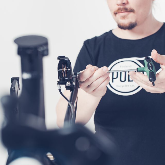
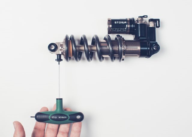
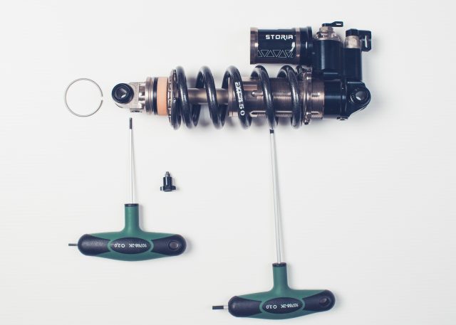
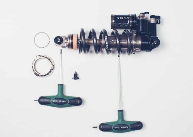
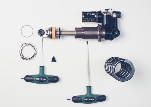
1. Use 2.0mm Allen key to remove the Rebound adjusting screw2. Use 3.0mm Allen key to loosen the spring preload3. Unscrew the preload plate and move the spring towards the top of the shock.4. Move the lower shock plate toward the spring. Remove the lock ring. You should be able to remove the lock ring without tools but if it seems to be too tight use some thin plastic or metallic tool to help and avoid harming the shock.5. Slide the lower shock plate towards the end of the shock and remove it.6. Now you should be able to slide the spring also of from the shock.
Assembly
1. Slide spring in so that it’ll connect to the upper spring plate.2. Slide the lower spring plate to its place3. Slide the lock ring back to its place4. Preload the spring. When the spring is contacting the upper spring plate (preload plate), turn by hand max 2 turns (max 2mm). Look that the 3mm hex screw is matching one of the body grooves. Tighten the 3mm hex screw.5. Put the rebound knob back to its place and use 2mm Allen key to tighten the knob.
If you did write your settings down before disassembly now you can readjust/recheck that you have the same settings than before the spring swap.
You can also find EXT owner and service manual from here